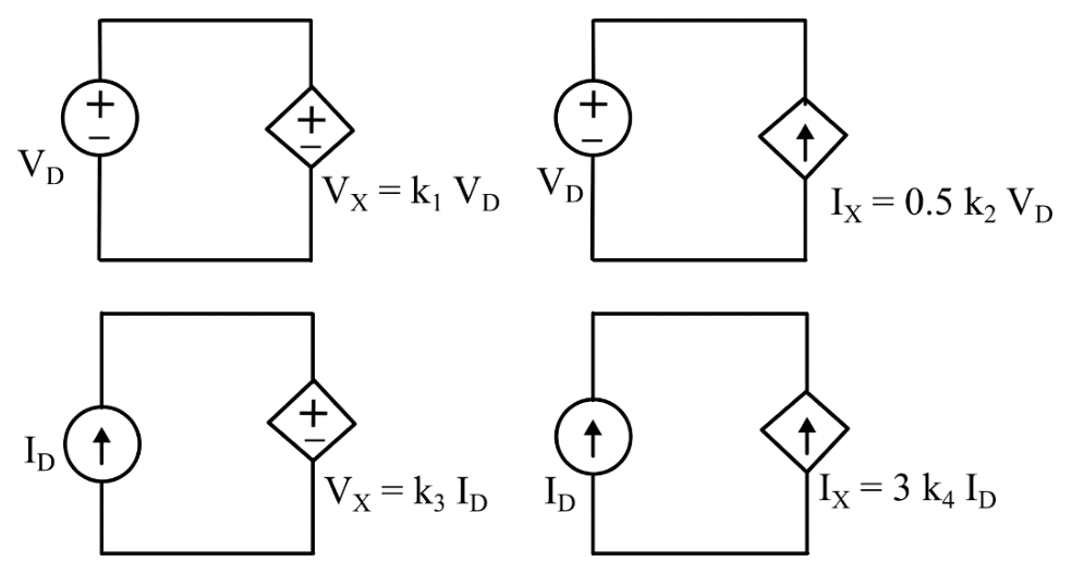
Correct answer: (A) $k_1=1,\ k_4=-1/3$, for all values of $k_2$ and $k_3$
Explanation
Circuit 1 has two ideal voltage sources directly in parallel, which is only consistent if they have the same value: $k_1V_D=V_D$, so $k_1=1$. Circuit 2 has a current source across a voltage source and Circuit 3 has a voltage source in series with a current source, so both are realizable for any $k_2$ and $k_3$. Circuit 4 has two ideal current sources in series but pointing in opposing directions around the loop, which requires $3k_4I_D=-I_D$, i.e. $k_4=-1/3$.
More Network Elements: Ideal voltage and current sources, dependent sources, R, L, C, M elements questions
GATE 2025 EE Q18– The I-V characteristics of the element between the nodes X and Y is best depicted by
GATE 2025 EE Q19– A nullator is defined as a circuit element where the voltage across the device and the…
GATE 2023 EE Q44– All the elements in the circuit shown in the following figure are ideal. Which of the…
GATE 2021 EE Q40– The input impedance, Z in(s), for the network shown is
GATE 2021 EE Q60– An air-core radio-frequency transformer as shown has a primary winding and a secondary…
GATE 2018 EE Q29– In the two-port network shown, the h 11 parameter (where, h 11=V 1I 1, when V 2=0) in ohms…