$I_A=572.812+j50.115$ A $I_B=-254.525-j459.175$ A $I_C=-207.083+j444.091$ A
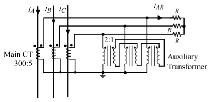
Given that the CTs are ideal with no saturation, and the turns ratio of the Main CT is 300:5 and that of the Auxiliary Transformer (YnΔ) is 2:1 on every phase, the value of $I_{AR}$, rounded off to three decimal places, is:
The main CTs (ratio 60:1) give secondary currents $I_A/60,\ I_B/60,\ I_C/60$. The Yn–Δ auxiliary transformer traps the zero-sequence current in its delta, so only the non-zero-sequence part reaches the relay branch: $I_{AR}=\dfrac{I_A-I_0}{60}$ with $I_0=\dfrac{I_A+I_B+I_C}{3}$. $I_A+I_B+I_C=111.204+j35.031$, so $I_0=37.068+j11.677$. $I_A-I_0=535.744+j38.438$ A. Dividing by 60: $8.929+j0.641=8.954\angle4.105^\circ$ A.
More Principles of over-current, differential, directional and distance protection; Circuit breakers questions
GATE 2026 EE Q40– The operating characteristic of a reactance relay is given by X1\ , where X is the…
GATE 2023 EE Q20– For the three-bus power system shown in the figure, the trip signals to the circuit…
GATE 2022 EE Q13– The most commonly used relay, for the protection of an alternator against loss of…
GATE 2020 EE Q18– A lossless transmission line with 0.2 pu reactance per phase uniformly distributed along…
GATE 2019 EE Q62– In a 132 kV system, the series inductance up to the point of circuit breaker location is…
GATE 2014 EE (EE1) Q25– A three-phase-to-ground fault occurs at F₁ or F₂ in the system shown. Bus-A voltages and…