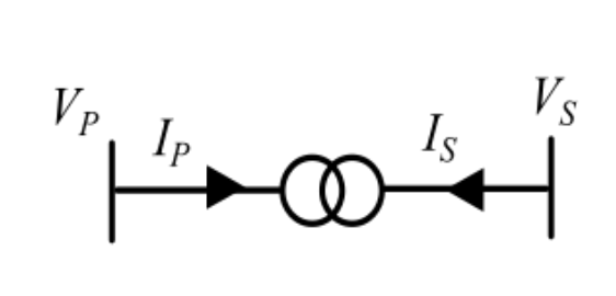
A three-phase two-winding transformer has a voltage transformation ratio $\dfrac{V_P}{V_S}=0.866+j0.5$, where $V_P$ is the primary side voltage in p.u., and $V_S$ is the secondary side voltage in p.u. $I_P$ and $I_S$ represent the currents injected into the primary and secondary sides of the transformer, respectively. The admittance corresponding to the leakage impedance of the transformer referred to the secondary is $y_t$ p.u. Neglect the magnetizing branch.
Let $a=\dfrac{V_P}{V_S}=0.866+j0.5$, with $|a|=1$. The secondary current is $I_S=y_t\left(V_S-\dfrac{V_P}{a}\right)$. An ideal transformer with a complex ratio conserves complex power, so $I_P=-\dfrac{I_S}{a^*}=\dfrac{y_t}{|a|^2}V_P-\dfrac{y_t}{a^*}V_S$. With $|a|=1$: $Y_{PP}=y_t$, $Y_{PS}=-\dfrac{y_t}{a^*}=-\dfrac{y_t}{0.866-j0.5}$, $Y_{SP}=-\dfrac{y_t}{a}=-\dfrac{y_t}{0.866+j0.5}$, $Y_{SS}=y_t$. The matrix is not symmetric, which matches option D.
More Per-unit quantities, Bus admittance matrix, Gauss-Seidel and Newton-Raphson load flow methods questions
GATE 2023 EE Q28– The bus admittance (Y bus) matrix of a 3-bus power system is given below. Y…
GATE 2023 EE Q41– The three-bus power system shown in the figure has one alternator connected to bus 2 which…
GATE 2021 EE Q19– Consider a power system consisting of N number of buses. Buses in this power system are…
GATE 2021 EE Q45– A 3-Bus network is shown. Consider generators as ideal voltage sources. If rows 1, 2 and 3…
GATE 2020 EE Q19– Out of the following options, the most relevant information needed to specify the real…
GATE 2020 EE Q39– Two buses, i and j, are connected with a transmission line of admittance Y, at the two…