GATE 2024 EE – Question 49
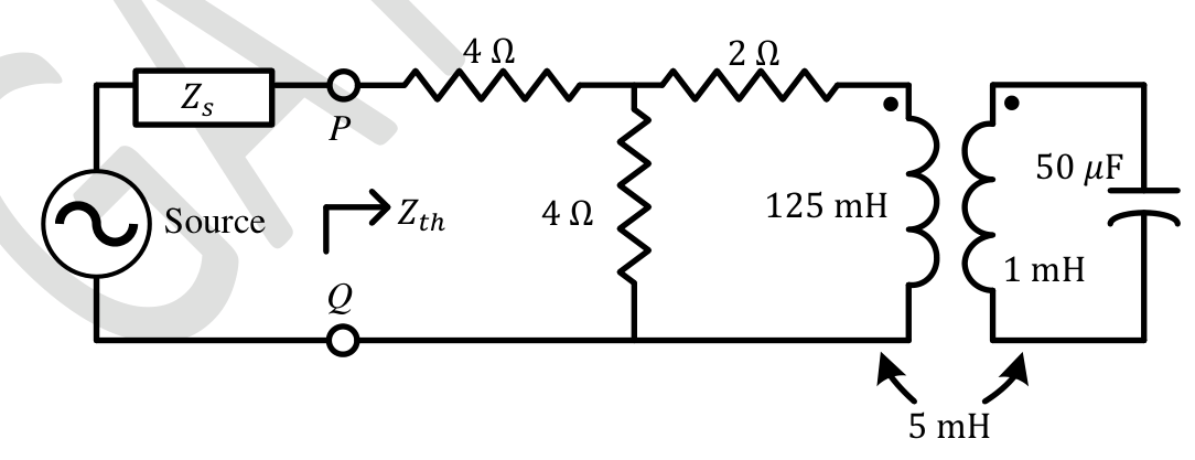
For the circuit shown in the figure, the source frequency is 5000 rad/sec. The mutual inductance between the magnetically coupled inductors is 5 mH with their self inductances being 125 mH and 1 mH. The Thevenin's impedance, $Z_{th}$, between the terminals P and Q in Ω is __________ (rounded off to 2 decimal places).
Practise this question in The GATE Grind →
Show answer and explanation
Correct answer: 5.30 to 5.36
Explanation
At 5000 rad/s: $\omega L_1=625\ \Omega$, $\omega L_2=5\ \Omega$, $\omega M=25\ \Omega$ and $\dfrac1{\omega C}=4\ \Omega$. The secondary loop is $L_2$ in series with $C$: $Z_2=j5-j4=j1\ \Omega$. The impedance reflected into the primary is $\dfrac{(\omega M)^2}{Z_2}=\dfrac{625}{j1}=-j625\ \Omega$, which cancels $j\omega L_1=j625$, so the coupled branch is a short circuit apart from the 2 Ω resistor. Looking in at PQ (source removed): $Z_{th}=4+\left(4\parallel2\right)=4+1.33=5.33\ \Omega$.