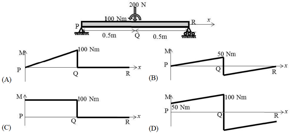
A simply supported beam PR of length 1 m has a downward force 200 N and counterclockwise couple 100 N m at its midpoint Q. Which bending-moment diagram is correct?
Taking counterclockwise moments about P gives $R_R(1)-200(0.5)+100=0$, hence R_R=0 and R_P=200 N. The bending moment rises linearly from zero at P to 100 N m immediately left of Q. The concentrated counterclockwise couple gives a downward jump of 100 N m; the moment is zero throughout QR. This is diagram A.
More Strength of materials: stress and strain, stress-strain curves, trusses, bars, beams and shafts, determinate and indeterminate questions
GATE 2019 AE Q59– A rigid uniform slab hangs symmetrically from three vertical cables of identical length…
GATE 2019 AE Q60– The pin-jointed right-isosceles truss shown has a 10 cm base. Each member has E=200 GPa…
GATE 2019 AE Q61– A solid circular shaft has factor of safety 2 under a given torque. A concentric hole of…
GATE 2024 AE Q53– In the figure shown below, the magnitude of internal force in member BC is N (rounded off…
GATE 2025 AE Q27– A simply supported horizontal beam is subjected to a distributed transverse load varying…
GATE 2025 AE Q30– In the given figure, plate ABCD in its undeformed configuration (solid line) is a rhombus…