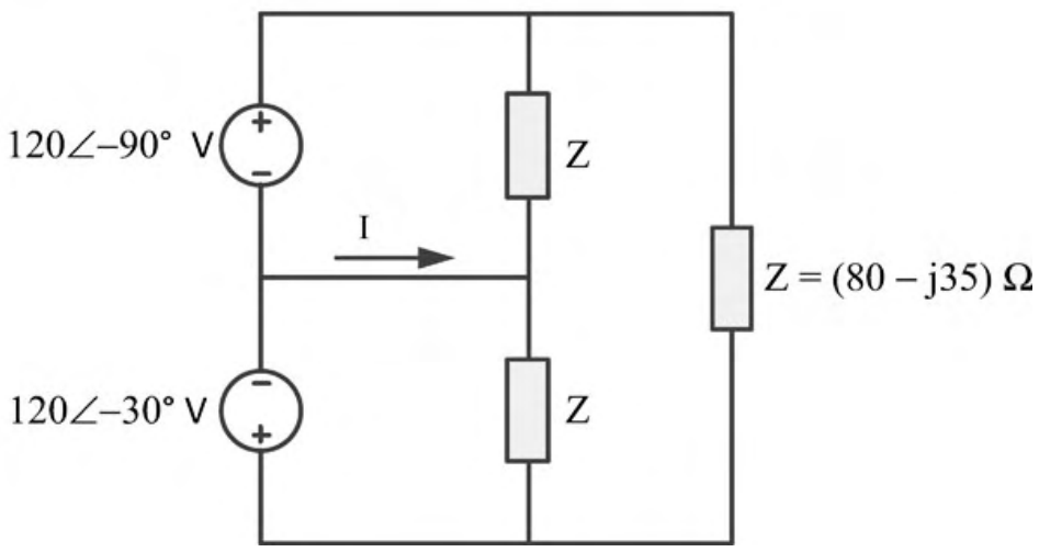
Take the common node of the two sources and the middle of the two $Z$ impedances as the reference, which are joined by the wire carrying $I$. The top and bottom nodes are then at $V_T=120\angle-90^\circ=-j120$ V and $V_B=120\angle-30^\circ=103.9-j60$ V. The current in the wire is $I=-\frac{V_T+V_B}{Z}=-\frac{103.9-j180}{80-j35}=-\frac{207.8\angle-60^\circ}{87.3\angle-23.63^\circ}=-2.38\angle-36.37^\circ=2.38\angle143.63^\circ$ A.
More Sinusoidal Steady State Analysis questions
GATE 2019 EC Q40– In the circuit shown, if v(t)=2(1000t) volts, R=1\ k and C=1\ F, then the steady-state…
GATE 2018 EC Q45– For the circuit given in the figure, the voltage V c (in volts) across the capacitor is
GATE 2016 EC Q41– A network consisting of a finite number of linear resistor (R), inductor (L), and…
GATE 2015 EC Q16– In the circuit shown, at resonance, the amplitude of the sinusoidal voltage (in Volts)…
GATE 2015 EC Q42– In the given circuit, the maximum power (in Watts) that can be transferred to the load R L…
GATE 2017 EC Q17– In the circuit shown, the positive angular frequency (in radians per second) at which the…