GATE 2018 EE – Question 18
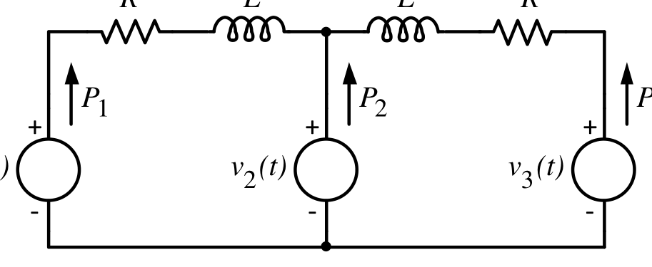
In the figure, the voltages are $v_1(t)=100\cos(\omega t)$, $v_2(t)=100\cos(\omega t+\pi/18)$ and $v_3(t)=100\cos(\omega t+\pi/36)$. The circuit is in sinusoidal steady state, and $R\ll\omega L$. $P_1$, $P_2$ and $P_3$ are the average power outputs. Which one of the following statements is true?
Practise this question in The GATE Grind →
Show answer and explanation
Correct answer: (C) $P_1<0,P_2>0,P_3<0$
Explanation
With $R\ll\omega L$ the real power flows from the source that leads in phase towards those that lag. $v_2$ leads both $v_1$ and $v_3$, so it supplies power ($P_2>0$), while $v_1$ (most lagging) and $v_3$ absorb it ($P_1<0$, $P_3<0$).