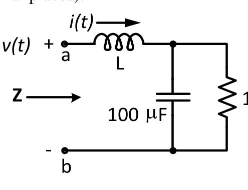
The voltage $v(t)$ across the terminals $a$ and $b$ as shown in the figure, is a sinusoidal voltage having a frequency $\omega=100$ radian/s. When the inductor current $i(t)$ is in phase with the voltage $v(t)$, the magnitude of the impedance $Z$ (in $\Omega$) seen between the terminals $a$ and $b$ is ________ (up to 2 decimal places).
The parallel $R$-$C$ part is $\frac{100}{1+j100\times100\ \mu\text{F}\times100}=\frac{100}{1+j}=50-j50\ \Omega$. For the current to be in phase with $v(t)$ the total impedance must be real, so $\omega L=50\ \Omega$ cancels the $-j50$. Then $Z=50\ \Omega$.
More Transient response of DC and AC networks, sinusoidal steady-state analysis, resonance, two port networks, balanced three phase circuits, star-delta transformation, complex power and power factor in AC circuits questions
GATE 2016 EE Q49– In the circuit shown, switch S 2 has been closed for a long time. At time t = 0 switch S 1…
GATE 2016 EE Q62– In the circuit shown below, the supply voltage is 10(1000t) volts. The peak value of the…
GATE 2016 EE Q64– The circuit below is excited by a sinusoidal source. The value of R, in , for which the…
GATE 2015 EE Q30– An inductor is connected in parallel with a capacitor as shown in the figure. As the…
GATE 2015 EE Q55– The circuit shown in the figure has two sources connected in series. The instantaneous…
GATE 2015 EE Q56– In a linear two-port network, when 10 V is applied to Port 1, a current of 4 A flows…