GATE 2026 EE – Question 48
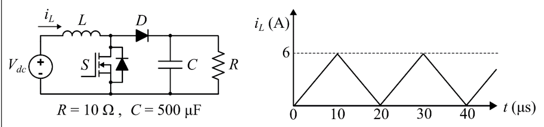
Consider the boost converter circuit shown. Assume that the semiconductor devices are ideal. In steady state, the inductor current rises linearly from 0 A to 6 A in the first 10 μs and then falls linearly from 6 A to 0 A in the next 10 μs of every switching cycle as shown. The load resistance $R$ is 10 Ω and the capacitance $C$ is 500 μF.
Neglect the ripple in the output voltage. What is the input voltage $V_{dc}$?
Practise this question in The GATE Grind →
Show answer and explanation
Correct answer: (C) 7.5 V
Explanation
The switch is on for 10 μs and off for 10 μs, so $D=0.5$. The inductor current ramps from 0 to 6 A and back, so its average is 3 A, which is the average input current. The current returns to zero exactly at the end of the cycle (boundary conduction), so $V_o=\dfrac{V_{dc}}{1-D}=2V_{dc}$. Equating input and output power with lossless devices: $V_{dc}\times3=\dfrac{(2V_{dc})^2}{10}$, so $3=0.4V_{dc}$ and $V_{dc}=7.5$ V.