GATE 2026 EE – Question 47
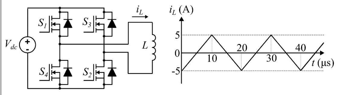
Consider the single-phase voltage source inverter circuit feeding an inductive load ($L$). Assume that the power MOSFET switches are ideal. $S_1$ and $S_2$ are switched on during the first 10 μs, and $S_3$ and $S_4$ are switched on during the next 10 μs in a switching cycle. The switches in a same leg are thus switched in a complementary fashion. Neglect the dead time. The waveform of the inductor current ($i_L$) in the steady state is triangular with a peak value of 5 A as shown.
The rms value of the current through the switch $S_1$ is:
Practise this question in The GATE Grind →
Show answer and explanation
Correct answer: (B) 2.04 A
Explanation
$S_1$ is on for the first 10 μs of each 20 μs cycle and carries the load current then (an ideal MOSFET conducts in both directions). During this interval $i_L$ rises linearly from −5 A to +5 A. $I_{rms}^2=\dfrac{1}{20}\int_0^{10}i^2dt=\dfrac{1}{20}\cdot10\cdot\dfrac{5^2}{3}=4.167$, so $I_{rms}=2.04$ A.