GATE 2025 EE – Question 49
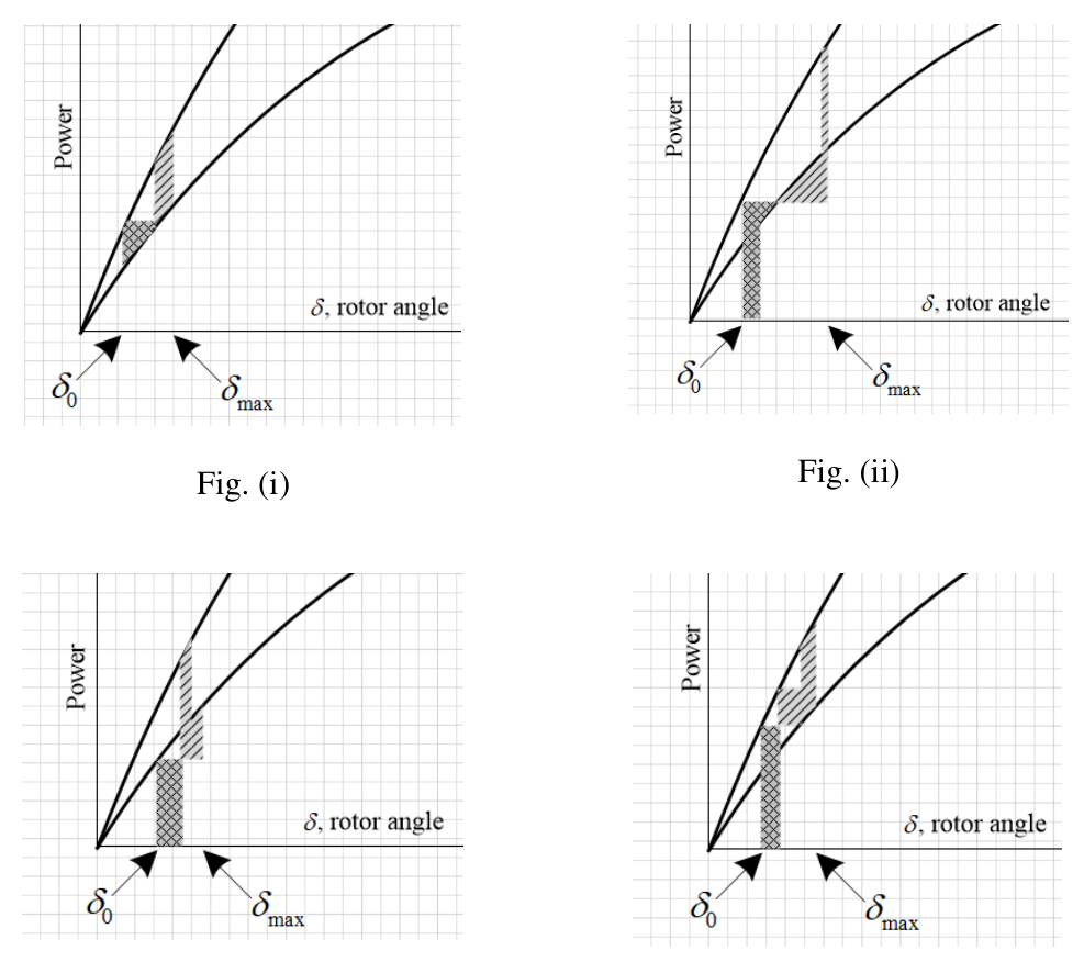
In the system shown below, the generator was initially supplying power to the grid. A temporary LLLG bolted fault occurs at F very close to circuit breaker 1. The circuit breakers open to isolate the line. The fault self-clears. The circuit breakers reclose and restore the line. Which one of the following diagrams best indicates the rotor accelerating and decelerating areas?
Practise this question in The GATE Grind →
Show answer and explanation
Correct answer: (B) Fig. (ii)
Explanation
A bolted three-phase fault at the generator terminals reduces the electrical power output to zero, and while the breakers are open the line carries no power either. So the accelerating area is the full rectangle between the axis and the mechanical power $P_m$ from $\delta_0$ to the clearing angle. After reclosing, the original power-angle curve is restored, and the decelerating area lies between that curve and $P_m$ up to $\delta_{max}$. Only Fig. (ii) shows a rectangle from zero power followed by a decelerating wedge between the restored curve and $P_m$.