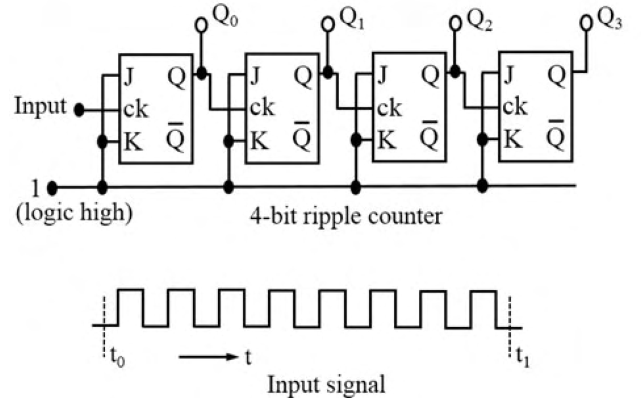
A four-bit ripple counter uses four flip-flops with J = K = 1; each Q output clocks the next flip-flop. Falling clock edges trigger changes. All outputs are low at $t=t_0$. For the input waveform shown, the outputs at $t=t_1$ are
J = K = 1 makes each stage toggle on its active falling clock edge. Cascading the Q outputs produces a binary up counter with $Q_0$ the least significant bit. Eight falling edges occur between the marked times, so the counter advances from 0000 to 1000 in $Q_3Q_2Q_1Q_0$ order. Thus $Q_3=1$ and the other three outputs are zero, option B.
More Basics of digital logic circuits, combinational and sequential circuits, flip- flops, timers, counters, registers, A/D and D/A conversion. questions
GATE 2024 PH Q24– Consider the following circuit: Suppose the input signal P is and the input signal Q is…
GATE 2024 PH Q32– The minimum number of basic logic gates to realize B(A+B)+A( B+A) is (in integer).
GATE 2025 PH Q19– A logic gate circuit is shown in the figure below. The correct combination for the input…
GATE 2025 PH Q41– An α particle is scattered from an Au target at rest as shown in the figure. D1 and D2 are…
GATE 2026 PH Q44– Considering the circuit and the associated signals measured at different pins (numbered as…
GATE 2023 PH Q24– Which one of the following options is CORRECT for the given logic circuit?