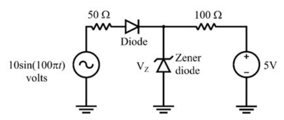
The circuit has ideal diodes, a 5 V Zener breakdown voltage, a 10 sin(100πt) V input through 50 Ω, and a 100 Ω branch to a +5 V source as shown. The power dissipated in the 100 Ω resistor, in watts, is
The ordinary diode admits positive input excursions. The Zener clamps the junction to at most +5 V, and the 5 V source biases the other end of the 100 Ω resistor to +5 V. With the diode off, that same source holds the junction at 5 V through the resistor. Thus both ends remain at 5 V, no current flows through the 100 Ω resistor, and its power is zero, A.
More Diodes and transistor circuits: Types of diode and their applications, BJT and MOSFET circuits, biasing, power dissipation, DC and small signal analysis, frequency response, feedback, amplifier design questions
GATE 2020 IN Q61– Assume all diodes in the circuit are ideal. Find current Iₖ through the 3 kΩ resistor in…