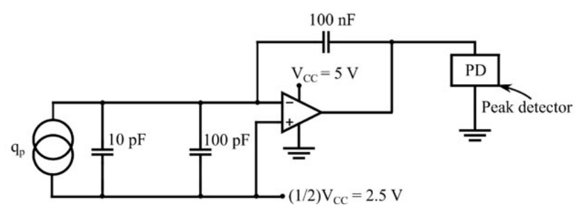
The charge-amplifier circuit shown uses an ideal op-amp powered by VCC = 5 V and biased at VCC/2. A piezoelectric sensor generates $q_p=0.1\sin(10000\pi t)$ μC. Find the peak-detector output after 10 cycles in V, to one decimal place.
The inverting charge amplifier has feedback capacitance 100 nF. Its output AC amplitude is $q_{peak}/C_f=0.1\ \mu\mathrm C/0.1\ \mu\mathrm F=1$ V about the 2.5 V bias. Thus output spans 1.5 to 3.5 V without reaching the supply rails. An ideal positive peak detector settles to the maximum 3.5 V. The input sensor and cable capacitances do not change ideal charge gain.
More Piezoelectric electromagnetic and Hall sensors: Piezoelectric, electromagnetic and Hall effect sensors and their signal conditioning circuits questions
GATE 2026 IN Q63– A current-carrying semiconductor of thickness 0.7 mm is placed in a transverse magnetic…
GATE 2025 IN Q13– The working of the hand-held metal detector most widely used by security personnel for…
GATE 2024 IN Q29– The figure shows the readout circuit of a piezoelectric sensor. A generated charge q p…