GATE 2023 EE – Question 29
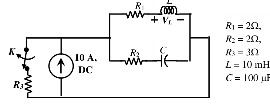
The value of parameters of the circuit shown in the figure are
$R_1=2\ \Omega$, $R_2=2\ \Omega$, $R_3=3\ \Omega$, $L=10$ mH, $C=100\ \mu$F
For time $t<0$, the circuit is at steady state with the switch ‘K’ in closed condition. If the switch is opened at $t=0$, the value of the voltage across the inductor ($V_L$) at $t=0^+$ in Volts is ____________ (Round off to 1 decimal place).
Practise this question in The GATE Grind →
Show answer and explanation
Correct answer: 7.96 to 8.04
Explanation
For $t<0$ (DC steady state) the inductor is a short and the capacitor is open, so the load branch is just $R_1$ (2 Ω). The 10 A source divides between $R_3$ (3 Ω) and $R_1$: $i_L=10\times\dfrac{3}{5}=6$ A. The capacitor carries no current, so $v_C=6\times2=12$ V. At $t=0^+$ the switch opens, so all 10 A flows into the load network. The inductor current stays 6 A and $v_C$ stays 12 V, so the remaining 4 A flows through $R_2$ and $C$. The node voltage is $v=12+4\times2=20$ V, so $V_L=20-6\times2=8.0$ V.