GATE 2023 EE – Question 41
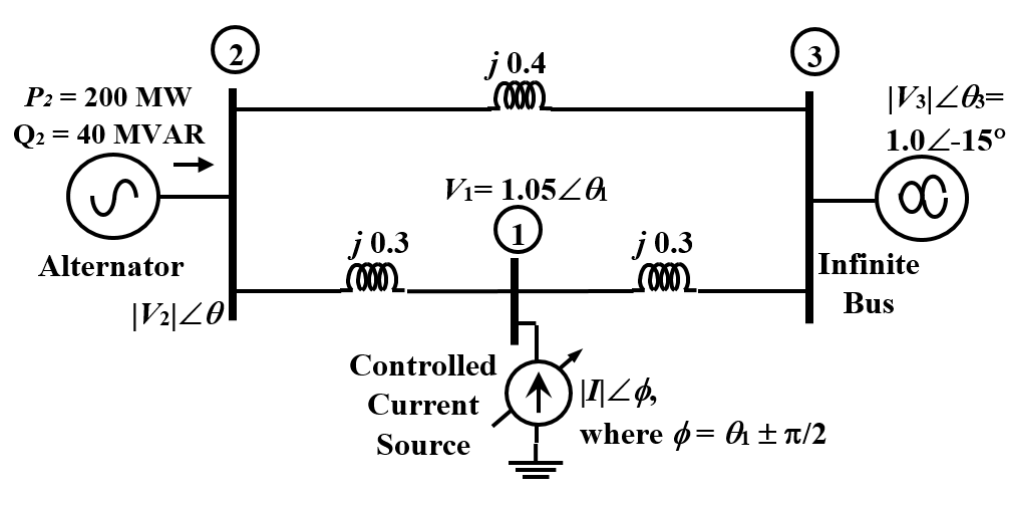
The three-bus power system shown in the figure has one alternator connected to bus 2 which supplies 200 MW and 40 MVAr power. Bus 3 is infinite bus having a voltage of magnitude $|V_3|=1.0$ p.u. and angle of −15°. A variable current source $|I|\angle\phi$ is connected at bus 1 and controlled such that the magnitude of the bus 1 voltage is maintained at 1.05 p.u. and the phase angle of the source current, $\phi=\theta_1\pm\frac\pi2$, where $\theta_1$ is the phase angle of the bus 1 voltage. The three buses can be categorized for load flow analysis as
Practise this question in The GATE Grind →
Show answer and explanation
Correct answer: (D) Bus 1: P−|V| bus; Bus 2: P−Q bus; Bus 3: Slack bus
Explanation
Bus 3 is the infinite bus with fixed magnitude and angle: the slack bus. At bus 1 the current is 90° out of phase with the voltage, so the source injects only reactive power ($P=0$), while its magnitude is controlled to hold $|V_1|=1.05$ pu: a $P$–$|V|$ bus. Bus 2 has specified $P=200$ MW and $Q=40$ MVAr: a $P$–$Q$ bus.