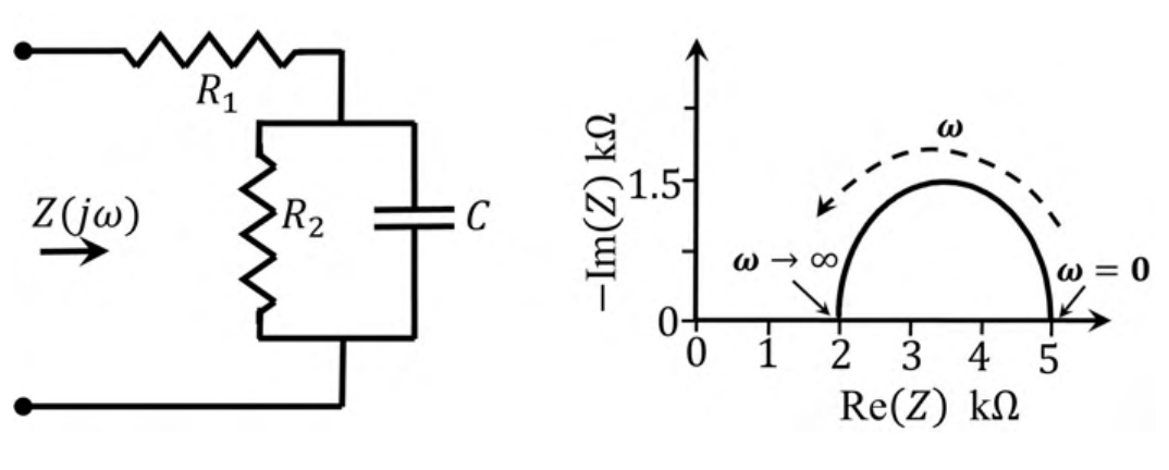
For the circuit shown, the locus of the impedance $Z(j\omega)$ is plotted as $\omega$ increases from zero to infinity. The values of $R_1$ and $R_2$ are:
$Z=R_1+\frac{R_2}{1+j\omega R_2C}$. At $\omega=0$ the capacitor is open and $Z=R_1+R_2=5\ \text{k}\Omega$; at $\omega\to\infty$ it is a short and $Z=R_1=2\ \text{k}\Omega$. So $R_1=2\ \text{k}\Omega$ and $R_2=3\ \text{k}\Omega$. The locus is a semicircle of diameter $R_2=3\ \text{k}\Omega$, whose radius $1.5\ \text{k}\Omega$ matches the peak in the plot.
More Sinusoidal Steady State Analysis questions
GATE 2022 EC Q39– Consider the circuit shown in the figure with input V(t) in volts. The sinusoidal steady…
GATE 2020 EC Q26– The current in the RL-circuit shown below is i(t)=10(5t-/4) A. The value of the inductor…