GATE 2021 EC – Question 18
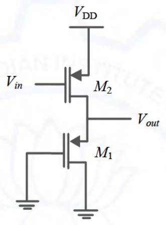
In the circuit shown in the figure, the transistors $M_1$ and $M_2$ are operating in saturation. The channel length modulation coefficients of both the transistors are non-zero. The transconductance of the MOSFETs $M_1$ and $M_2$ are $g_{m1}$ and $g_{m2}$, respectively, and the internal resistance of the MOSFETs $M_1$ and $M_2$ are $r_{o1}$ and $r_{o2}$, respectively.
Ignoring the body effect, the ac small signal voltage gain ($\partial V_{out}/\partial V_{in}$) of the circuit is
Practise this question in The GATE Grind →
Show answer and explanation
Correct answer: (D) $-g_{m2}\left(\frac{1}{g_{m1}}\|r_{o1}\|r_{o2}\right)$
Explanation
Both devices are p-channel. $M_2$ (gate driven by $V_{in}$, source at $V_{DD}$) is the common-source amplifier. $M_1$ has its gate grounded (ac ground) and its source at $V_{out}$, so the load it presents is $\frac{1}{g_{m1}}\|r_{o1}$. The total resistance at the output is $\frac{1}{g_{m1}}\|r_{o1}\|r_{o2}$, so $A_v=-g_{m2}\left(\frac1{g_{m1}}\|r_{o1}\|r_{o2}\right)$.