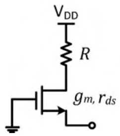
Apply a test voltage $v$ at the source with the gate grounded and the top of $R$ at ac ground. Then $v_{gs}=-v$ and the drain voltage is $v_d=-i_dR$. The drain current (drain to source) is $i_d=g_mv_{gs}+\frac{v_d-v}{r_{ds}}=-g_mv-\frac{i_dR+v}{r_{ds}}$, so $i_d\left(1+\frac{R}{r_{ds}}\right)=-v\left(g_m+\frac1{r_{ds}}\right)$ and $i_d=-v\frac{1+g_mr_{ds}}{r_{ds}+R}$. The current entering the source is $-i_d$, so $R_{eq}=\frac{v}{-i_d}=\frac{r_{ds}+R}{1+g_mr_{ds}}$.
More BJT and MOSFET Amplifiers questions
GATE 2020 EC Q54– In the voltage regulator shown below, V I is the unregulated input at 15 V. Assume V…
GATE 2019 EC Q19– The correct circuit representation of the structure shown in the figure is
GATE 2019 EC Q50– In the circuits shown, the threshold voltage of each nMOS transistor is 0.6 V. Ignoring…
GATE 2019 EC Q60– Consider a long-channel MOSFET with a channel length 1\ m and width 10\ m. The device…
GATE 2019 EC Q64– In the circuit shown, the threshold voltages of the pMOS ( V tp ) and nMOS (V tn)…
GATE 2019 EC Q65– In the circuit shown, V 1=0 and V 2=V dd. The other relevant parameters are mentioned in…