GATE 2018 EC – Question 20
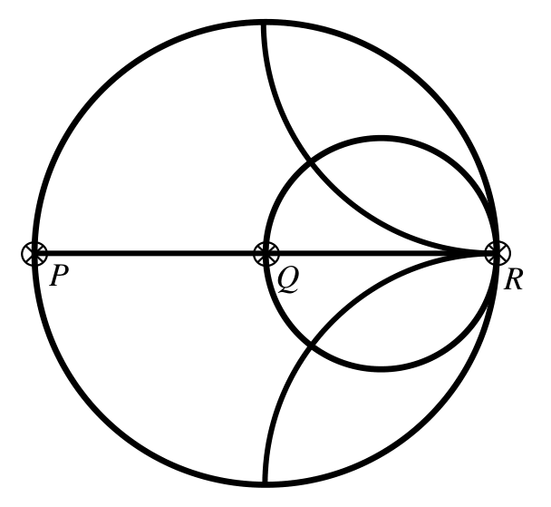
The points $P$, $Q$, and $R$ shown on the Smith chart (normalized impedance chart) in the following figure represent:
Practise this question in The GATE Grind →
Show answer and explanation
Correct answer: (C) P: Short Circuit, Q: Matched Load, R: Open Circuit
Explanation
On the Smith chart, the left end of the real axis ($z=0$, $\Gamma=-1$) is a short circuit, the centre ($z=1$, $\Gamma=0$) is the matched load and the right end ($z=\infty$, $\Gamma=+1$) is an open circuit. So P is a short circuit, Q is matched and R is an open circuit.