GATE 2018 EE – Question 25
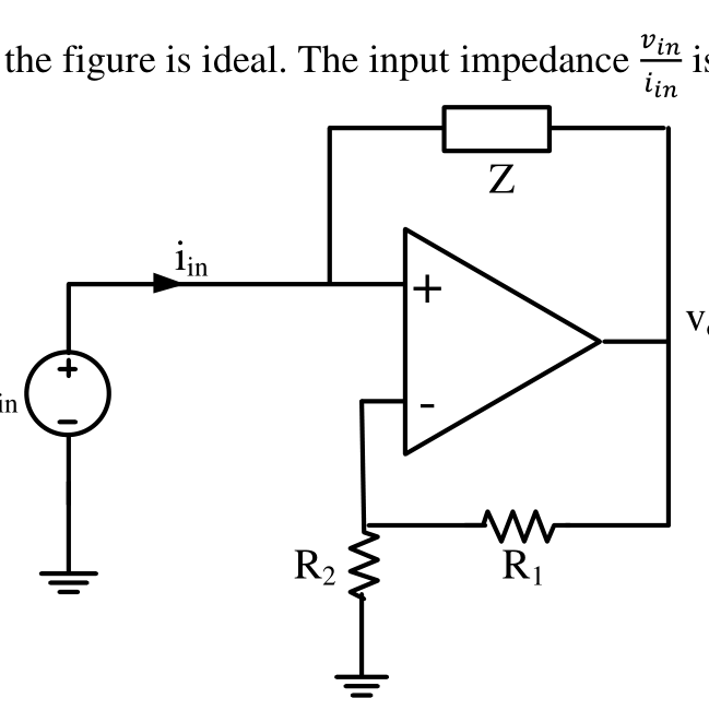
The op-amp shown in the figure is ideal. The input impedance $\dfrac{v_{in}}{i_{in}}$ is given by
Practise this question in The GATE Grind →
Show answer and explanation
Correct answer: (B) $-Z\dfrac{R_2}{R_1}$
Explanation
The input drives the non-inverting terminal, with $Z$ connecting it to the output. The inverting terminal is at $v_{in}$ through the divider, so $v_{in}=\frac{R_2}{R_1+R_2}V_o$, i.e. $V_o=v_{in}\frac{R_1+R_2}{R_2}$. The current through $Z$ is $i_{in}=\frac{v_{in}-V_o}{Z}=-\frac{v_{in}R_1}{R_2Z}$, so $\frac{v_{in}}{i_{in}}=-Z\frac{R_2}{R_1}$.