GATE 2015 EC – Question 49
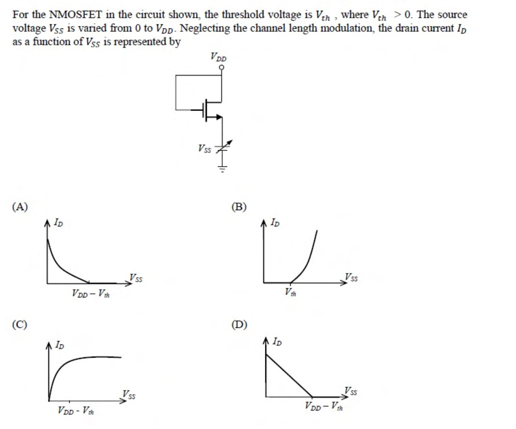
For the NMOSFET in the circuit shown, the threshold voltage is $V_{th}$, where $V_{th} > 0$. The source voltage $V_{SS}$ is varied from 0 to $V_{DD}$. Neglecting the channel length modulation, the drain current $I_D$ as a function of $V_{SS}$ is represented by
Practise this question in The GATE Grind →
Show answer and explanation
Correct answer: (A) Plot (A): a curve falling from a maximum at $V_{SS} = 0$ to zero at $V_{DD} - V_{th}$
Explanation
With the gate tied to the drain, the transistor is always in saturation, so $I_D = \frac{k}{2}(V_{DD} - V_{SS} - V_{th})^2$. This is a parabola that is largest at $V_{SS} = 0$ and falls to zero at $V_{SS} = V_{DD} - V_{th}$, and it stays zero beyond that. That is a curve, not a straight line, which is plot (A).