GATE 2017 EC – Question 30
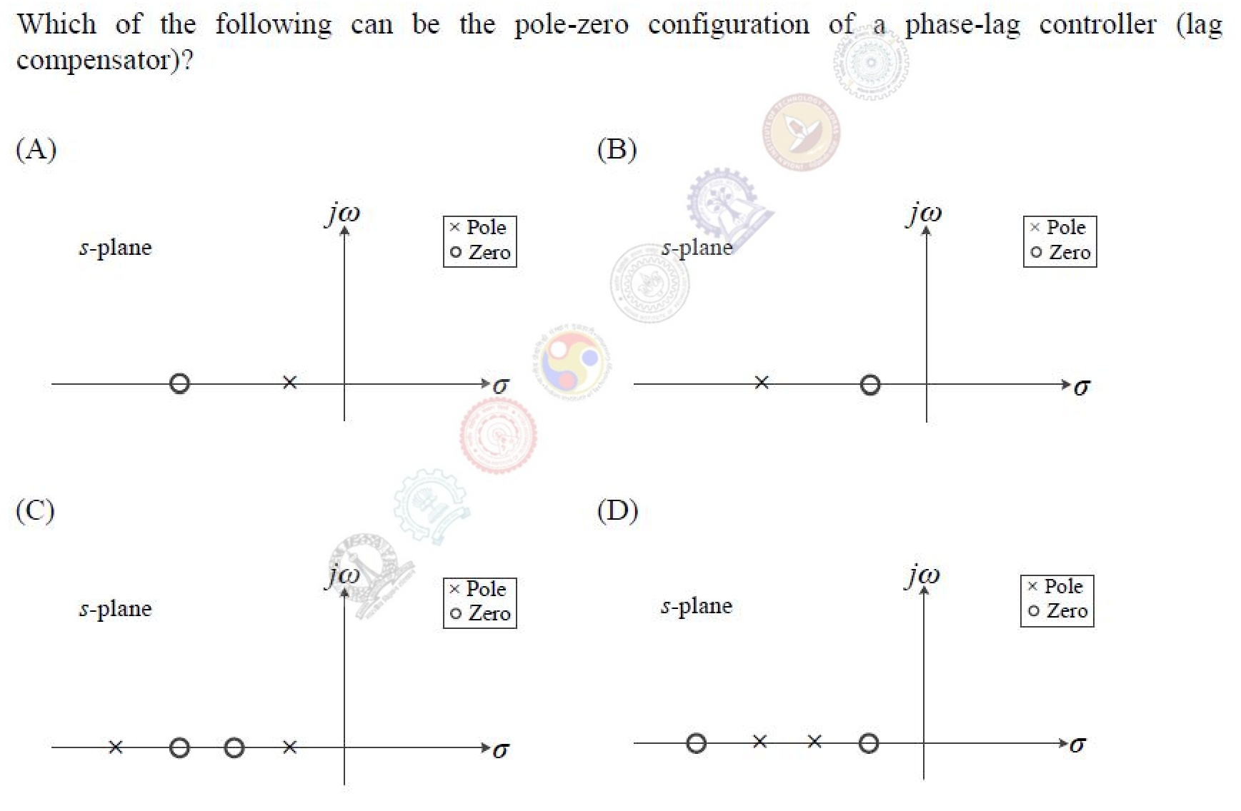
Which of the following can be the pole-zero configuration of a phase-lag controller (lag compensator)?
Practise this question in The GATE Grind →
Show answer and explanation
Correct answer: (A) Plot (A)
Explanation
A lag compensator has the form $\frac{s + z}{s + p}$ with the pole closer to the origin than the zero ($p < z$). On the negative real axis that means the pole is to the right of the zero, nearer the origin. That is the pattern in plot (A). In plot (B) the zero is nearer the origin, which is a lead compensator.