The GATE Grind

GATE 2017 EE – Question 45

Analog and Digital Electronics · Operational amplifiers: characteristics and applications · 2 marks · Multiple choice

The approximate transfer characteristic for the circuit shown below with an ideal operational amplifier and diode will be
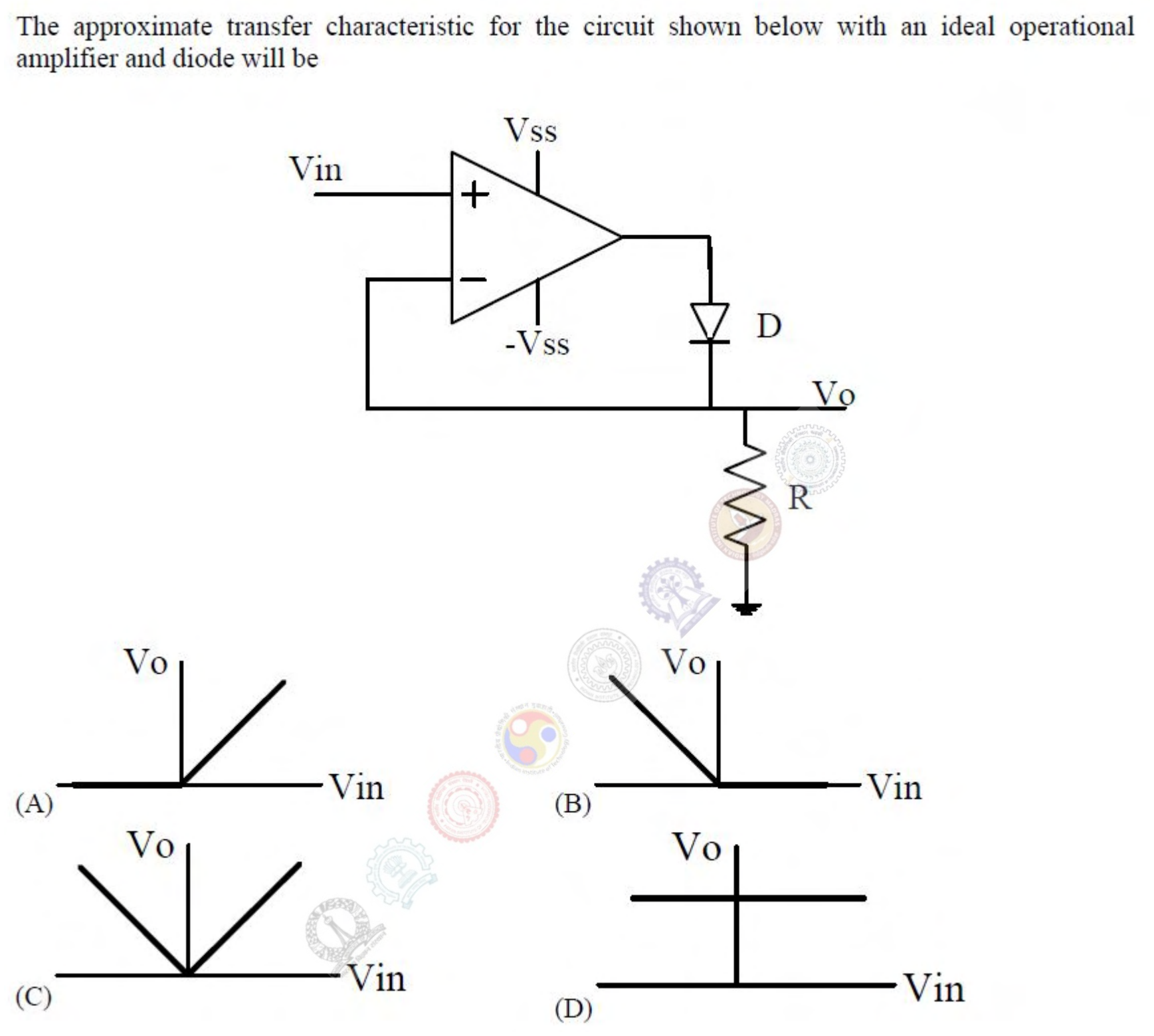
The input $V_{in}$ drives the non-inverting input of an ideal op-amp powered from $\pm V_{ss}$. The output of the op-amp feeds a diode D, and the diode output is the output voltage $V_o$, which is also connected back to the inverting input and to ground through a resistor R. Four candidate characteristics of $V_o$ against $V_{in}$ are shown: (A) zero for negative $V_{in}$ and a line of slope 1 for positive $V_{in}$; (B) a line of slope $-1$ for negative $V_{in}$ and zero for positive $V_{in}$; (C) a V shape through the origin; (D) a constant value.
  1. Characteristic (A): $V_o = 0$ for $V_{in} < 0$ and $V_o = V_{in}$ for $V_{in} > 0$
  2. Characteristic (B)
  3. Characteristic (C)
  4. Characteristic (D)

Practise this question in The GATE Grind →

Show answer and explanation

Correct answer: (A) Characteristic (A): $V_o = 0$ for $V_{in} < 0$ and $V_o = V_{in}$ for $V_{in} > 0$

Explanation

When $V_{in}$ is positive the op-amp output rises, the diode conducts, and the feedback makes $V_o = V_{in}$. When $V_{in}$ is negative the op-amp output goes to its negative limit, the diode is reverse biased, and no current flows, so $V_o = 0$ through R. This is an ideal half-wave rectifier.