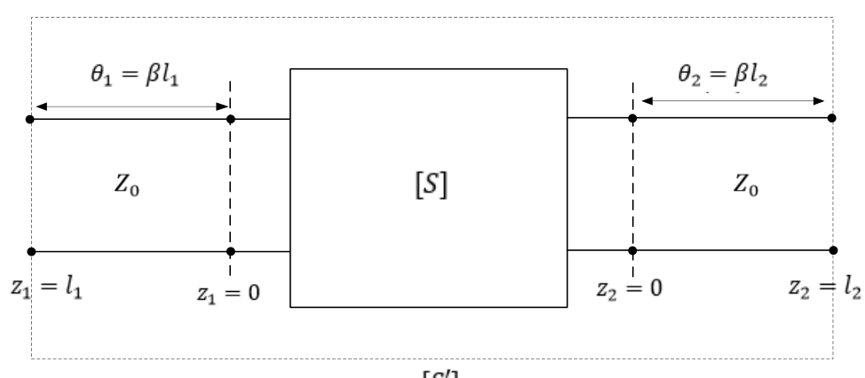
with reference to $Z_0$. Two lossless transmission line sections of electrical lengths $\theta_1=\beta l_1$ and $\theta_2=\beta l_2$ are added to the input and output ports for measurement purposes, respectively. The S-parameters $[S']$ of the resultant two port network is
Adding a lossless line of electrical length $\theta$ at a port moves the reference plane outward. A wave going out and returning (reflection) picks up the phase $e^{-j\theta}$ twice, so $S_{11}'=S_{11}e^{-j2\theta_1}$ and $S_{22}'=S_{22}e^{-j2\theta_2}$. A transmitted wave crosses both lines once, so $S_{21}'=S_{21}e^{-j(\theta_1+\theta_2)}=S_{12}'$ (for a reciprocal network).
More Transmission Lines questions
GATE 2023 EC Q52– The standing wave ratio on a 50 Ω lossless transmission line terminated in an unknown load…
GATE 2023 EC Q54– The following circuit(s) representing a lumped element equivalent of an infinitesimal…
GATE 2021 EC Q45– The impedance matching network shown in the figure is to match a lossless line having…
GATE 2020 EC Q23– The impedances Z=jX, for all X in the range (-,), map to the Smith chart as
GATE 2020 EC Q31– A transmission line of length 3/4 and having a characteristic impedance of 50\ is…
GATE 2018 EC Q20– The points P, Q, and R shown on the Smith chart (normalized impedance chart) in the…