GATE 2023 EE – Question 60
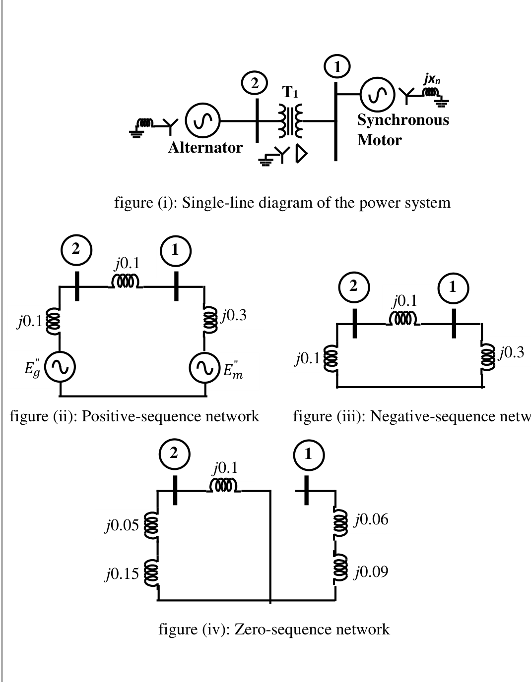
The two-bus power system shown in figure (i) has one alternator supplying a synchronous motor load through a Y-Δ transformer. The positive, negative and zero-sequence diagrams of the system are shown in figures (ii), (iii) and (iv), respectively. All reactances in the sequence diagrams are in p.u. For a bolted line-to-line fault (fault impedance = zero) between phases ‘b’ and ‘c’ at bus 1, neglecting all pre-fault currents, the magnitude of the fault current (from phase ‘b’ to ‘c’) in p.u. is ______________ (Round off to 2 decimal places).
Practise this question in The GATE Grind →
Show answer and explanation
Correct answer: 7.18 to 7.26
Explanation
Seen from bus 1, the positive-sequence network has the motor reactance $j0.3$ in parallel with the path through the line, transformer side and generator: $j0.1+j0.1=j0.2$. $Z_1=0.3\parallel0.2=j0.12$ pu, and the negative-sequence network has the same value, $Z_2=j0.12$. For a line-to-line fault $I_{a1}=\dfrac{1}{Z_1+Z_2}=\dfrac{1}{0.24}=4.167$ pu and $I_{fault}=\sqrt3\,|I_{a1}|=7.22$ pu.