Home › Previous year questions › GATE 2016 EC (EC2) › Question 18GATE 2016 EC (EC2) – Question 18 Networks, Signals and Systems · Sinusoidal Steady State Analysis · 1 mark · Numerical answer
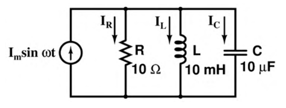
The figure shows a parallel RLC circuit with a sinusoidal current source. At resonance, the ratio $|I_L|/|I_R|$ of the inductor and resistor current phasor magnitudes is ________.
Practise this question in The GATE Grind →
Show answer and explanation Correct answer: 0.30 to 0.34
Explanation At parallel resonance, $\omega_0=1/\sqrt{LC}$. All three branches have the same voltage magnitude V, so $|I_L|/|I_R|=R/(\omega_0L)$.
With R=10 Ω, L=10 mH and C=10 μF, $\omega_0=3162.28$ rad/s. Thus the ratio is $10/(3162.28\cdot0.01)=$ **0.31623**, within 0.30–0.34.
More Sinusoidal Steady State Analysis questions GATE 2016 EC (EC3) Q19 – For the RLC circuit shown, v i(t)=2(200t)+4(500t) V. The output voltage is GATE 2026 EC Q31 – Consider the circuit shown in the Figure, where the input v i(t) is in Volt. The average… GATE 2026 EC Q39 – In the given circuit, L=1 μH and C=1 μF. The phasor diagram for I C and I L is also shown.… GATE 2025 EC Q20 – Let i C, i L, and i R be the currents flowing through the capacitor, inductor, and… GATE 2025 EC Q39 – In the circuit below, M 1 is an ideal AC voltmeter and M 2 is an ideal AC ammeter. The… GATE 2023 EC Q18 – A series RLC circuit has a quality factor Q of 1000 at a center frequency of 106 rad/s.… All Sinusoidal Steady State Analysis questions →