Home › Previous year questions › GATE 2026 EC › Question 39GATE 2026 EC – Question 39 Networks, Signals and Systems · Sinusoidal Steady State Analysis · 2 marks · Multiple choice
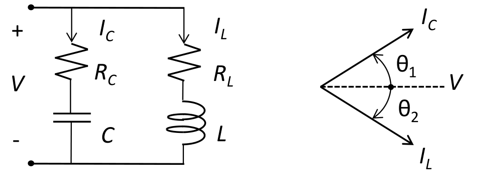
In the given circuit, $L=1$ μH and $C=1$ μF. The phasor diagram for $I_C$ and $I_L$ is also shown. Assume that the phase ($\theta_1+\theta_2$) is 90° at a frequency of 159.15 kHz. Among the following options, what is the nearest integer value of $R_C\times R_L$?
0 1 2 10 Practise this question in The GATE Grind →
Show answer and explanation Correct answer: (B) 1
Explanation With $\omega=159.15\text{ kHz}\times2\pi=10^6$ rad/s, $X_L=\omega L=10^6\times10^{-6}=1\ \Omega$ and $X_C=\dfrac1{\omega C}=1\ \Omega$.
From the phasor diagram, $\theta_1=\tan^{-1}\dfrac{X_C}{R_C}=\tan^{-1}\dfrac1{R_C}$ and $\theta_2=\tan^{-1}\dfrac{X_L}{R_L}=\tan^{-1}\dfrac1{R_L}$.
$\theta_1+\theta_2=90^\circ$ means $\tan\theta_1\tan\theta_2=1$, so $\dfrac1{R_CR_L}=1$ and $R_CR_L=1$.
More Sinusoidal Steady State Analysis questions GATE 2025 EC Q20 – Let i C, i L, and i R be the currents flowing through the capacitor, inductor, and… GATE 2025 EC Q39 – In the circuit below, M 1 is an ideal AC voltmeter and M 2 is an ideal AC ammeter. The… GATE 2023 EC Q18 – A series RLC circuit has a quality factor Q of 1000 at a center frequency of 106 rad/s.… GATE 2022 EC Q38 – For the circuit shown, the locus of the impedance Z(j) is plotted as increases from zero… GATE 2022 EC Q39 – Consider the circuit shown in the figure with input V(t) in volts. The sinusoidal steady… GATE 2020 EC Q26 – The current in the RL-circuit shown below is i(t)=10(5t-/4) A. The value of the inductor… All Sinusoidal Steady State Analysis questions →