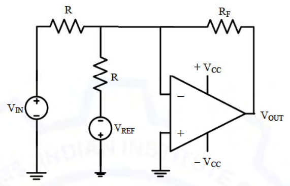
The op-amp is an inverting summer with equal resistors $R$ at the two inputs. The $V_{REF}$ source is connected with its positive terminal towards ground, so the branch applies $-V_{REF}$ to its resistor. Then $V_{OUT}=-\frac{R_F}{R}\left(V_{IN}-V_{REF}\right)$, which is zero when $V_{IN}=V_{REF}$.
More Op-amp Circuits questions
GATE 2021 EC Q55– A circuit with an ideal OPAMP is shown in the figure. A pulse V IN of 20 ms duration is…
GATE 2020 EC Q18– The components in the circuit shown below are ideal. If the op-amp is in positive feedback…
GATE 2020 EC Q28– In the circuit shown below, all the components are ideal. If V i is +2 V, the current I o…
GATE 2020 EC Q51– The components in the circuit given below are ideal. If R=2\ k and C=1\ F, the -3 dB…
GATE 2018 EC Q12– In the circuit shown below, the op-amp is ideal and the Zener voltage of the diode is 2.5…