Analog Circuits · Op-amp Circuits · 2 marks · Numerical answer
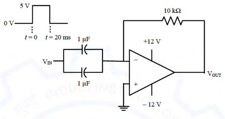
A circuit with an ideal OPAMP is shown in the figure. A pulse $V_{IN}$ of 20 ms duration is applied to the input. The capacitors are initially uncharged.
The output voltage $V_{OUT}$ of this circuit at $t=0^+$ (in integer) is ________ V.
With the capacitors in the input path the circuit is a differentiator: $V_{OUT}=-R_F(C_1+C_2)\frac{dV_{IN}}{dt}$. At $t=0$ the input steps from 0 V to 5 V, so the derivative is an impulse and the ideal output would be an infinite negative spike. The output is limited by the supply to the negative saturation level, so $V_{OUT}(0^+)=-12$ V.
More Op-amp Circuits questions
GATE 2020 EC Q18– The components in the circuit shown below are ideal. If the op-amp is in positive feedback…
GATE 2020 EC Q28– In the circuit shown below, all the components are ideal. If V i is +2 V, the current I o…
GATE 2020 EC Q51– The components in the circuit given below are ideal. If R=2\ k and C=1\ F, the -3 dB…
GATE 2018 EC Q12– In the circuit shown below, the op-amp is ideal and the Zener voltage of the diode is 2.5…