GATE 2018 EC – Question 12
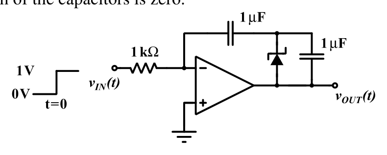
In the circuit shown below, the op-amp is ideal and the Zener voltage of the diode is 2.5 volts. At the input, unit step voltage is applied, i.e. $v_{IN}(t)=u(t)$ volts. Also, at $t=0$, the voltage across each of the capacitors is zero.
The time $t$, in milliseconds, at which the output voltage $v_{OUT}$ crosses $-10$ V is
Practise this question in The GATE Grind →
Show answer and explanation
Correct answer: (C) 7.5
Explanation
The inverting input is a virtual ground, so the $1\ \text{k}\Omega$ resistor gives a constant current $i=\frac{1\text{ V}}{1\text{ k}\Omega}=1$ mA for $t>0$. This current flows through the first capacitor $C_1$ and then into the parallel combination of the second capacitor $C_2$ and the Zener diode. The diode is oriented so that it breaks down (at 2.5 V) when the voltage across $C_2$ builds up in the direction of this current.
Each $1\ \mu$F capacitor charges at $\frac{i}{C}=1$ V per ms, so $v_{C_1}=t$ and $v_{C_2}=t$ (with $t$ in ms) until $v_{C_2}$ reaches 2.5 V at $t=2.5$ ms. After that the Zener takes the current and $v_{C_2}$ stays at 2.5 V.
Since $v_{OUT}=-(v_{C_1}+v_{C_2})$:
- for $t<2.5$ ms, $v_{OUT}=-2t$;
- for $t>2.5$ ms, $v_{OUT}=-(t+2.5)$.
Setting $v_{OUT}=-10$ V gives $t+2.5=10$, so $t=7.5$ ms.