GATE 2016 EC – Question 24
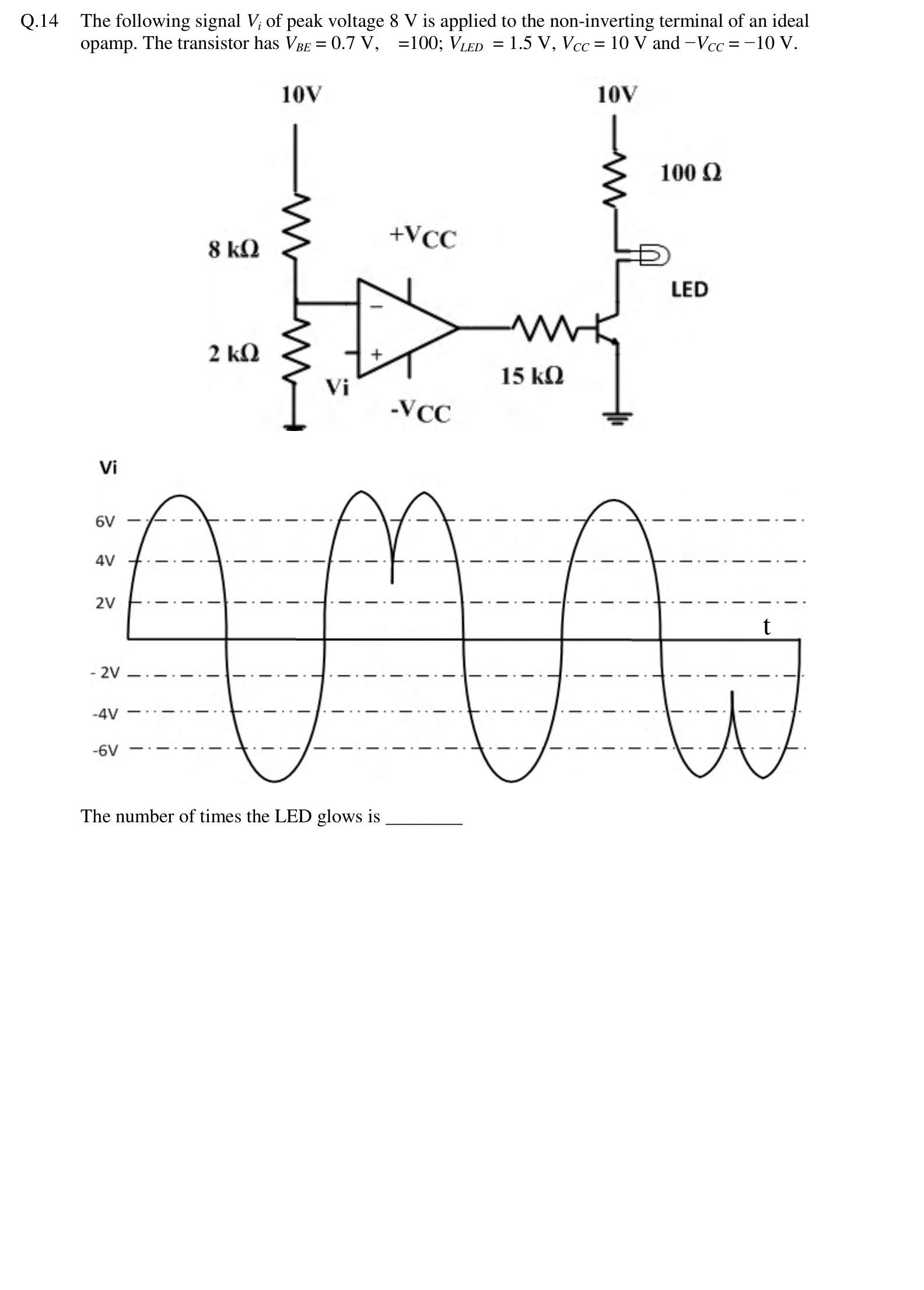
The following signal $V_i$ of peak voltage 8 V is applied to the non-inverting terminal of an ideal opamp. The transistor has $V_{BE} = 0.7$ V, $\beta = 100$; $V_{LED} = 1.5$ V, $V_{CC} = 10$ V and $-V_{CC} = -10$ V.
[Figure: The inverting input of the op-amp is held by a divider of 8 kΩ and 2 kΩ between 10 V and ground. The op-amp output drives the base of a transistor through 15 kΩ, and the transistor switches an LED in series with a 100 Ω resistor from 10 V. The input $V_i$ is a sine wave of peak 6 V, with three positive lobes. The first lobe is a single hump, the second lobe has a shallow dip in the middle that stays above 2 V, and the third lobe is a single hump.]
The number of times the LED glows is ________
Practise this question in The GATE Grind →
Show answer and explanation
Correct answer: 2.9 to 3.1
Explanation
The divider puts the inverting input at $10 \times \frac{2}{8 + 2} = 2$ V. The op-amp output goes high, and turns the transistor and LED on, whenever $V_i > 2$ V. The signal has three positive lobes that rise above 2 V. The dip in the middle of the second lobe stays above 2 V, so the LED stays on through it. The LED therefore glows 3 times.