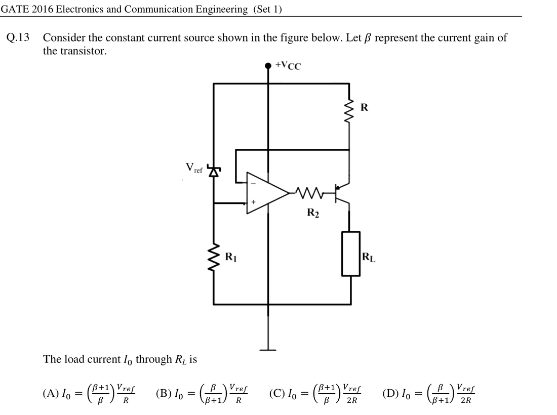
The op-amp forces the emitter node to match the reference, so the voltage across $R$ is $V_{ref}$ and the emitter current is $I_E = \frac{V_{ref}}{R}$. The load current is the collector current, $I_0 = I_C = \frac{\beta}{\beta + 1} I_E = \left(\frac{\beta}{\beta + 1}\right)\frac{V_{ref}}{R}$.
More Op-amp Circuits questions
GATE 2016 EC Q24– The following signal V i of peak voltage 8 V is applied to the non-inverting terminal of…
GATE 2016 EC Q25– Consider the oscillator circuit shown in the figure. The function of the network (shown in…
GATE 2016 EC Q50– An ideal opamp has voltage sources V 1, V 3, V 5, , V N-1 connected to the non-inverting…
GATE 2016 EC Q51– A p-i-n photodiode of responsivity 0.8 A/W is connected to the inverting input of an ideal…
GATE 2015 EC Q50– In the circuit shown, assume that the opamp is ideal. The bridge output voltage V 0 (in…
GATE 2015 EC Q51– The circuit shown in the figure has an ideal opamp. The oscillation frequency and the…