GATE 2020 EC – Question 20
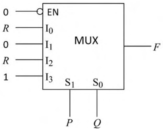
The figure below shows a multiplexer where $S_1$ and $S_0$ are the select lines, $I_0$ to $I_3$ are the input data lines, EN is the enable line, and $F(P,Q,R)$ is the output. $F$ is
Practise this question in The GATE Grind →
Show answer and explanation
Correct answer: (A) $PQ+\bar QR$.
Explanation
EN is active-low and tied to 0, so the multiplexer is enabled. With $S_1=P$ and $S_0=Q$, the inputs are $I_0=R$, $I_1=0$, $I_2=R$ and $I_3=1$. So $F=\bar P\bar QR+\bar PQ\cdot0+P\bar QR+PQ\cdot1=\bar QR(\bar P+P)+PQ=PQ+\bar QR$.