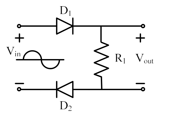
Correct answer: (A) $V_{out}=V_{in}$ for $V_{in}>0$
Explanation
For $V_{in}>0$ the current flows from the source through $D_1$, the resistor $R_1$ and then back through $D_2$, which are both forward biased, so $V_{out}=V_{in}$. For $V_{in}<0$ both diodes are reverse biased and $V_{out}=0$.
More Simple diode circuits: clipping, clamping, rectifiers questions
GATE 2021 EE Q34– In the circuit shown, the input V i is a sinusoidal AC voltage having an RMS value of 230…
GATE 2021 EE Q35– In the circuit shown, a 5 V Zener diode is used to regulate the voltage across load R 0.…
GATE 2021 EE Q61– A 100 Hz square wave, switching between 0 V and 5 V, is applied to a CR high-pass filter…
GATE 2020 EE Q40– Consider the diode circuit shown below. The diode, D, obeys the current-voltage…
GATE 2020 EE Q41– A non-ideal diode is biased with a voltage of -0.03 V, and a diode current of I 1 is…
GATE 2020 EE Q62– A non-ideal Si-based pn junction diode is tested by sweeping the bias applied across its…