The GATE Grind

GATE 2015 EE – Question 30

Electric Circuits · Transient response of DC and AC networks, sinusoidal steady-state analysis, resonance, two port networks, balanced three phase circuits, star-delta transformation, complex power and power factor in AC circuits · 1 mark · Multiple choice

An inductor is connected in parallel with a capacitor as shown in the figure. As the frequency of current $i$ is increased, the impedance ($Z$) of the network varies as
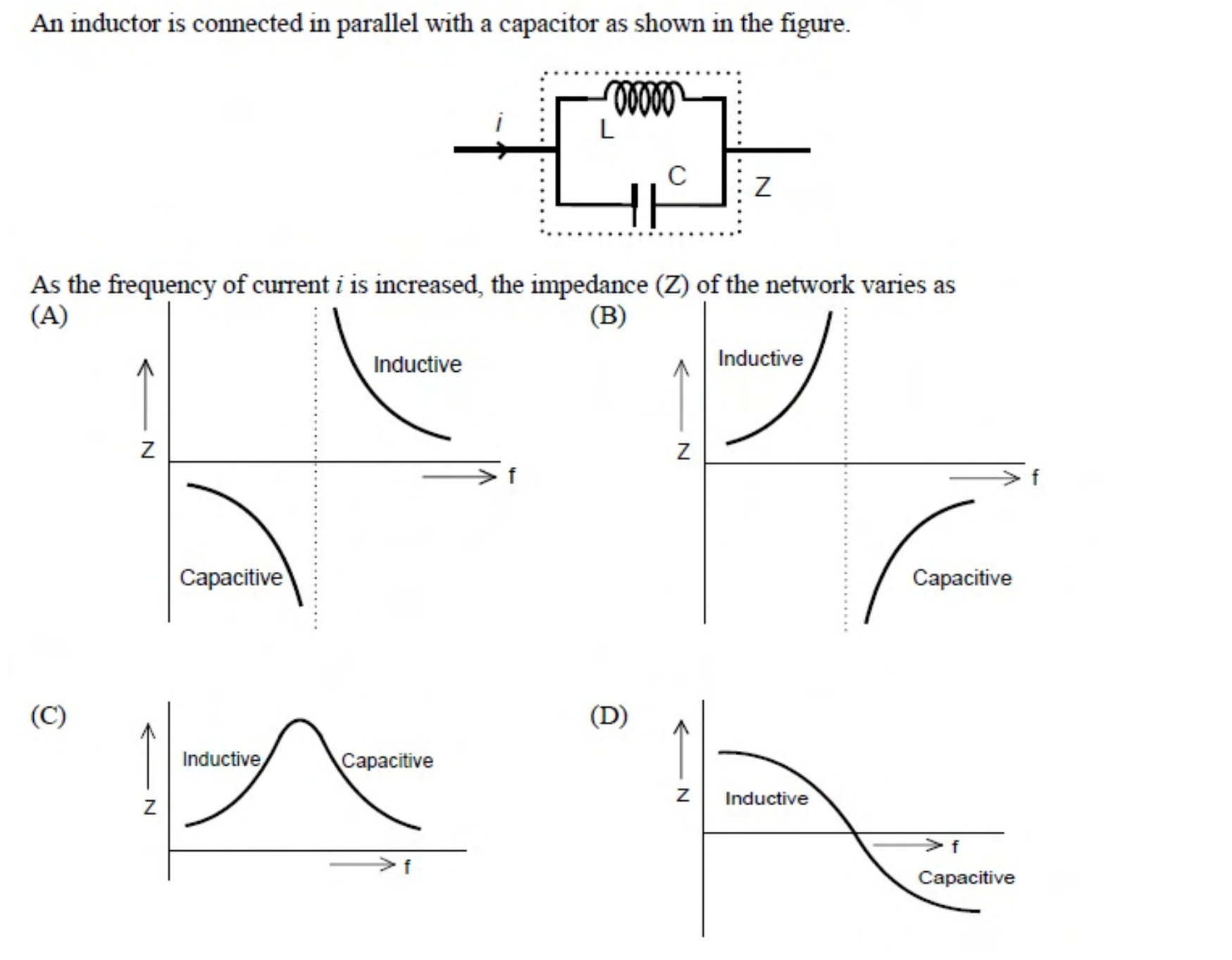
An inductor L in parallel with a capacitor C. Four candidate plots of $Z$ against $f$ are shown: (A) inductive above the axis, capacitive below it with the curves going up on the right of a vertical asymptote; (B) inductive rising to a vertical asymptote and capacitive coming up from below after it; (C) a single smooth peak; (D) a smooth falling curve through zero.
  1. Plot (A)
  2. Plot (B)
  3. Plot (C)
  4. Plot (D)

Practise this question in The GATE Grind →

Show answer and explanation

Correct answer: (B) Plot (B)

Explanation

At low frequency the inductor dominates, so the parallel network is inductive and its impedance rises with frequency. At the parallel resonance frequency the impedance becomes infinite. Beyond resonance the capacitor dominates, so the network is capacitive, and the impedance comes up from large negative values towards zero. That is plot (B).