GATE 2015 EE – Question 42
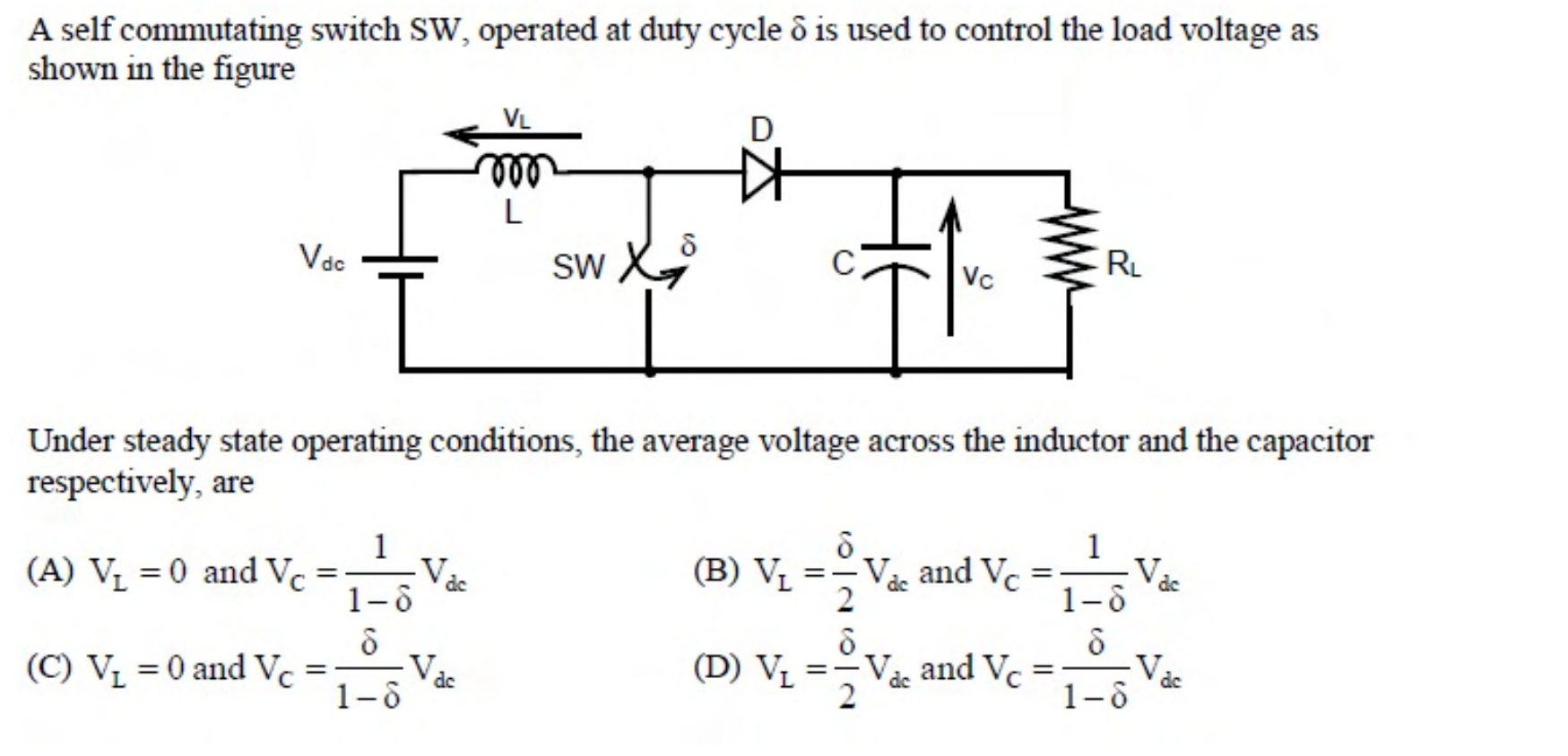
A self commutating switch SW, operated at duty cycle $\delta$ is used to control the load voltage as shown in the figure.
[Figure: A boost converter with source $V_{dc}$ in series with an inductor L, a switch SW across the line, a diode D, a capacitor C and a load $R_L$. $V_L$ is the inductor voltage and $V_C$ is the capacitor voltage.]
Under steady state operating conditions, the average voltage across the inductor and the capacitor respectively, are
Practise this question in The GATE Grind →
Show answer and explanation
Correct answer: (A) $V_L = 0$ and $V_C = \frac{1}{1 - \delta}V_{dc}$
Explanation
In steady state the average voltage across an inductor is zero. The circuit is a boost converter, whose output voltage is $\frac{V_{dc}}{1 - \delta}$.