GATE 2015 EE – Question 41
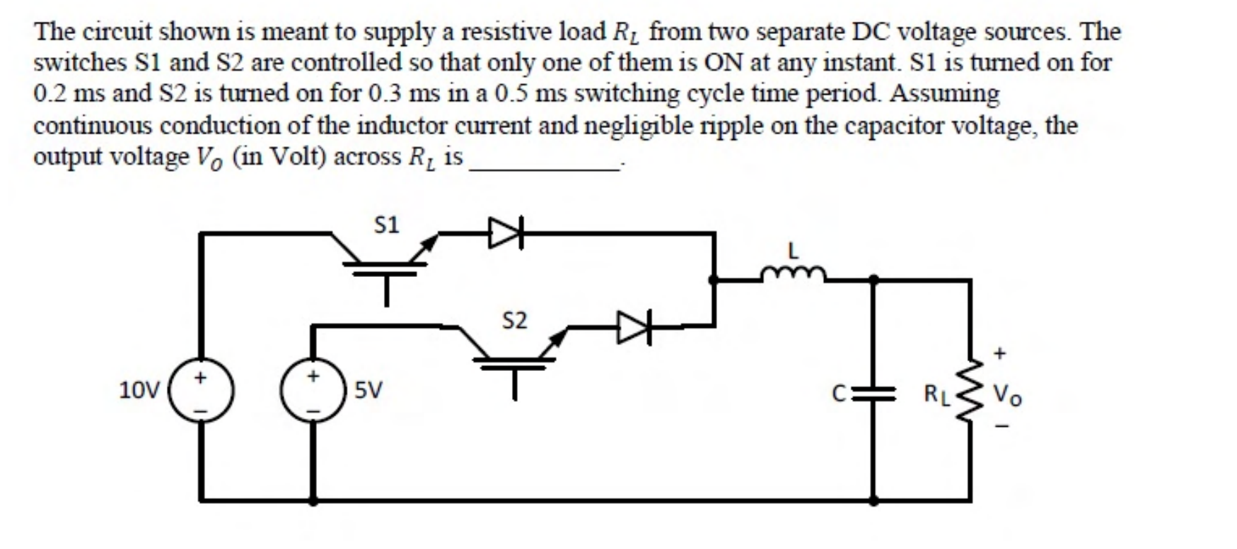
The circuit shown is meant to supply a resistive load $R_L$ from two separate DC voltage sources. The switches S1 and S2 are controlled so that only one of them is ON at any instant. S1 is turned on for 0.2 ms and S2 is turned on for 0.3 ms in a 0.5 ms switching cycle time period. Assuming continuous conduction of the inductor current and negligible ripple on the capacitor voltage, the output voltage $V_o$ (in Volt) across $R_L$ is ________.
Practise this question in The GATE Grind →
Show answer and explanation
Correct answer: 7
Explanation
The inductor voltage averages to zero over a cycle, so the output equals the average of the voltage applied to it. That is $V_o = \frac{0.2 \times 10 + 0.3 \times 5}{0.5} = \frac{2 + 1.5}{0.5} = 7$ V.