GATE 2014 EE (EE1) – Question 61
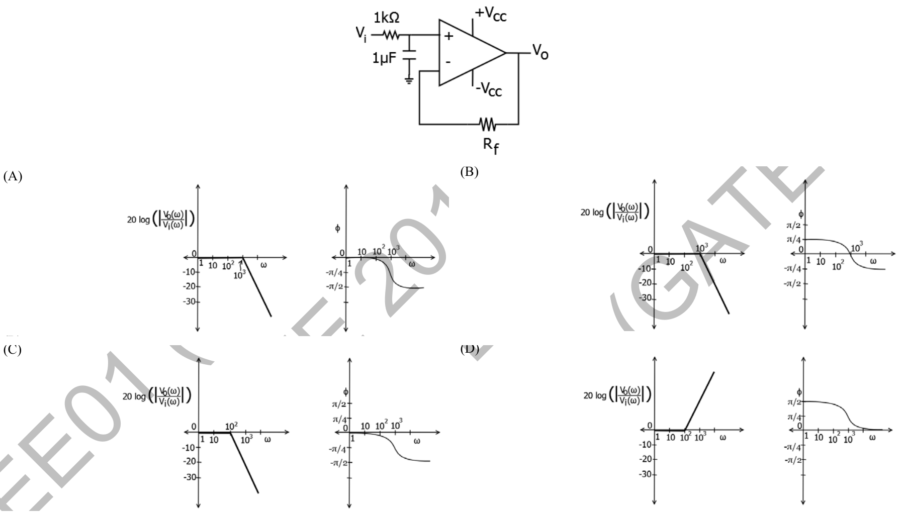
For the ideal op-amp circuit shown, which alternative gives correct Bode magnitude and phase plots for V₀(ω)/V_i(ω)?
Practise this question in The GATE Grind →
Show answer and explanation
Correct answer: (A) Plots A
Explanation
Ideal negative feedback and zero input current make the op-amp a voltage follower even with feedback resistor RF. Its non-inverting input is the RCnode, so H(s)=1/[1+s(1kΩ)(1µF)]=1/(1+0.001s). The pole is1000rad/s, magnitude slope changes0to−20dB/decade, and phase goes0to−π/2. These are the plots in **A**.