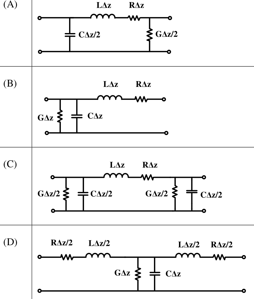
A transmission-line section of length $\Delta z$ has series $R\Delta z,\ L\Delta z$ and shunt $G\Delta z,\ C\Delta z$. The L-section in (B), the symmetric $\pi$-section in (C) (shunt elements split equally at both ends) and the symmetric T-section in (D) (series elements split equally on both sides) all contain exactly these totals in valid topologies. In (A) the shunt capacitance and conductance are placed at opposite ends of the series branch, which is not a standard equivalent section.
More Transmission Lines questions
GATE 2021 EC Q45– The impedance matching network shown in the figure is to match a lossless line having…
GATE 2020 EC Q23– The impedances Z=jX, for all X in the range (-,), map to the Smith chart as
GATE 2020 EC Q31– A transmission line of length 3/4 and having a characteristic impedance of 50\ is…
GATE 2018 EC Q20– The points P, Q, and R shown on the Smith chart (normalized impedance chart) in the…
GATE 2018 EC Q31– A lossy transmission line has resistance per unit length R=0.05\ /m. The line is…
GATE 2016 EC Q35– The propagation constant of a lossy transmission line is (2 + j5) m-1 and its…