GATE 2026 EE – Question 33
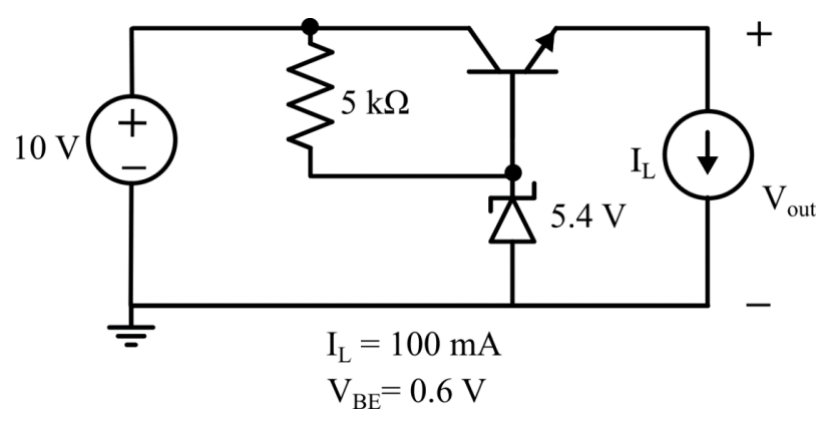
In the linear regulator circuit shown, the base to emitter voltage $V_{BE}$ of the BJT is 0.6 V. The Zener diode clamps the base voltage to 5.4 V. Ignore the biasing current of the Zener diode and BJT.
The maximum possible efficiency of the regulator circuit is ___________ %.
(Round off to one decimal place)
Practise this question in The GATE Grind →
Show answer and explanation
Correct answer: 47.76 to 48.24
Explanation
The output is $V_{out}=5.4-0.6=4.8$ V. With the biasing currents ignored, the input current equals the load current $I_L$, so $\eta=\dfrac{V_{out}I_L}{V_{in}I_L}=\dfrac{4.8}{10}=48.0\%$.