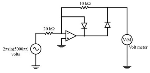
The ideal-op-amp precision-rectifier circuit shown is driven by $2\pi\sin(5000\pi t)$ V. Find the reading in volts of its 1 Hz bandwidth PMMC voltmeter.
The diode arrangement produces a half-wave rectified output. Its conducting-path gain magnitude is $R_f/R_{in}=10/20=1/2$, so the output pulse peak is $(1/2)(2\pi)=\pi$ V. The PMMC meter with 1 Hz bandwidth responds to the DC mean of these much faster pulses. A half-wave sine of peak A has mean A/π, giving $\pi/\pi=1$ V.
More Operational amplifiers and applications: Ideal and practical op-amps, adder, subtractor, integrator, differentiator, difference and instrumentation amplifiers, precision rectifier, active filters, comparators, Schmitt trigger questions
GATE 2020 IN Q49– In the shown circuit both op-amps are ideal and Vₓ = 0.5 mV. Find the steady-state output…
GATE 2026 IN Q45– In the circuit shown below, R=1\ k and R f=10\ k. If V in=100\ mV and the op-amps have…
GATE 2026 IN Q46– In the following active-filter circuit with ideal op-amps, R=1\ k and C=1\ F. The input V…
GATE 2025 IN Q20– For the ideal-opamp circuit shown, the ratio V/I is
GATE 2025 IN Q31– The circuits mentioned in the following options are realized using ideal opamp. Among…
GATE 2024 IN Q41– The opamps A 1,A 2 shown are ideal, except that A 1 has offset voltage V OS=1 mV. For V…