Analog Circuits · Op-amp Circuits · 1 mark · Multiple select
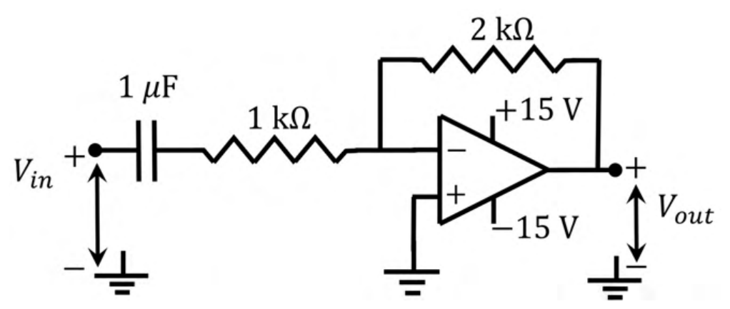
An ideal OPAMP circuit with a sinusoidal input is shown in the figure. The 3 dB frequency is the frequency at which the magnitude of the voltage gain decreases by 3 dB from the maximum value. Which of the options is/are correct?
Correct answer: (B) The circuit is a high pass filter.; (C) The 3 dB frequency is 1000 rad/s.
Explanation
This is an inverting amplifier with input impedance $R+\frac{1}{j\omega C}$ and feedback $2\ \text{k}\Omega$, so $\frac{V_o}{V_{in}}=-\frac{2\text{k}}{1\text{k}+1/(j\omega C)}$. The gain is small at low frequency and tends to $-2$ at high frequency, so it is a high-pass filter. The corner frequency is $\omega=\frac{1}{RC}=\frac{1}{1\text{k}\times1\ \mu\text{F}}=1000$ rad/s.
More Op-amp Circuits questions
GATE 2022 EC Q41– For the following circuit with an ideal OPAMP, the difference between the maximum and the…
GATE 2022 EC Q42– A circuit with an ideal OPAMP is shown. The Bode plot for the magnitude (in dB) of the…
GATE 2022 EC Q58– Consider the circuit shown with an ideal OPAMP. The output voltage V 0 is V (rounded off…
GATE 2021 EC Q19– For the circuit with an ideal OPAMP shown in the figure, V REF is fixed. If V OUT=1 volt…
GATE 2021 EC Q20– Consider the circuit with an ideal OPAMP shown in the figure. Assuming V IN V CC and V REF…
GATE 2021 EC Q55– A circuit with an ideal OPAMP is shown in the figure. A pulse V IN of 20 ms duration is…