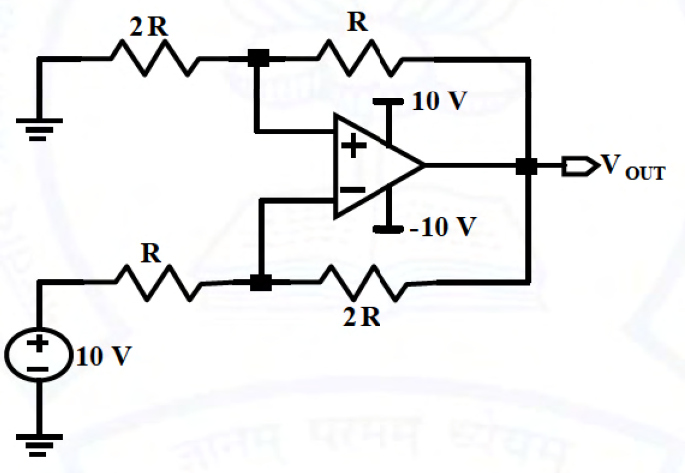
The shown op-amp has ±10 V supplies. Its non-inverting node connects to ground through 2R and output through R; its inverting node connects to +10 V through R and output through 2R. Find output in volts.
The non-inverting divider gives v+=2Vo/3. The inverting node gives v−=(20+Vo)/3. Thus the differential input is (Vo−20)/3, negative for every output between −10 and +10 V. The only consistent saturated state is Vo=−10 V. Equating the inputs would demand an unavailable twenty-volt output, so the linear virtual-short assumption is invalid.
More Operational Amplifiers questions
GATE 2020 BM Q38– For Vᵢₙ=10sin(2πt) applied to the circuit shown, which output waveform results? Both…
GATE 2026 BM Q48– For the ideal op-amp circuit shown, find input impedance looking into Vin.
GATE 2026 BM Q55– In the ideal instrumentation amplifier shown, one input-stage feedback resistor R* differs…
GATE 2025 BM Q15– The ideal op-amp circuit shown is driven by Vin=1 V and powered by ±15 V rails. Find Vout…
GATE 2025 BM Q52– Find the ideal summing op-amp output shown, in volts to the nearest integer. Inputs are 2…
GATE 2025 BM Q54– The oscillator shown has R=1 kΩ,R1=2 kΩ,R2=6 kΩ,C=0.1 μF. Find its oscillation frequency…