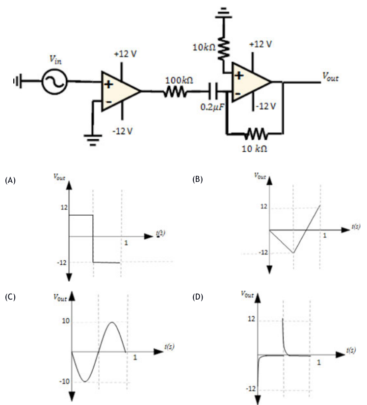
For Vᵢₙ=10sin(2πt) applied to the circuit shown, which output waveform results? Both op-amps have ±12 V supplies. The second stage contains 100 kΩ,0.2 μF and a 10 kΩ feedback resistor.
The first stage is an open-loop comparator, so the sinusoid becomes a ±12 V square wave. The second stage is an inverting practical differentiator: its input capacitor responds strongly at each transition and then decays through the resistive network, producing alternating transient spikes. D shows this response rather than a persistent square, triangular or sinusoidal waveform.
More Operational Amplifiers questions
GATE 2026 BM Q48– For the ideal op-amp circuit shown, find input impedance looking into Vin.
GATE 2026 BM Q55– In the ideal instrumentation amplifier shown, one input-stage feedback resistor R* differs…
GATE 2025 BM Q15– The ideal op-amp circuit shown is driven by Vin=1 V and powered by ±15 V rails. Find Vout…
GATE 2025 BM Q52– Find the ideal summing op-amp output shown, in volts to the nearest integer. Inputs are 2…
GATE 2025 BM Q54– The oscillator shown has R=1 kΩ,R1=2 kΩ,R2=6 kΩ,C=0.1 μF. Find its oscillation frequency…
GATE 2023 BM Q19– In the shown ideal-op-amp circuit, the parallel-plate capacitance is C= A/x, where ε is…