Analog Circuits · Diode Circuits · 1 mark · Numerical answer
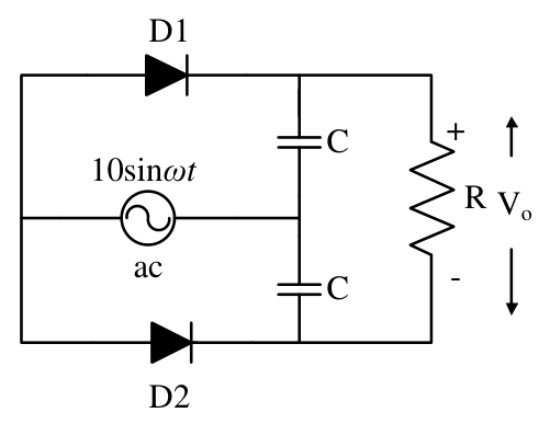
D1 and D2 are ideal, and the two capacitors are identical. RC is much greater than the ac period and the diodes do not break down in reverse bias. The steady-state output $V_O$ in volts is ________.
Both diodes point from the source's common terminal toward the upper and lower output nodes. On the relevant charging half-cycle, each identical capacitor is charged to the same voltage relative to the source's other terminal.
The upper and lower output nodes therefore attain equal potentials. Their difference across R is zero. This is not the opposite-diode orientation of a voltage doubler. Thus **$V_O=0$ V**.
More Diode Circuits questions
GATE 2016 EC (EC3) Q49– The Zener I–V curves are shown in Figure I and their series circuit in Figure II. As the…
GATE 2026 EC Q65– Consider the ideal diodes D1 and D2 as shown in the Figure with cut-in voltage V =0 Volt…
GATE 2025 EC Q57– All the diodes in the circuit given below are ideal. Which of the following plots is/are…
GATE 2025 EC Q61– The diode in the circuit shown below is ideal. The input voltage (in Volts) is given by V…
GATE 2024 EC Q23– In the circuit shown, the n:1 step-down transformer and the diodes are ideal. The diodes…
GATE 2024 EC Q35– As shown in the circuit, the initial voltage across the capacitor is 10 V, with the switch…