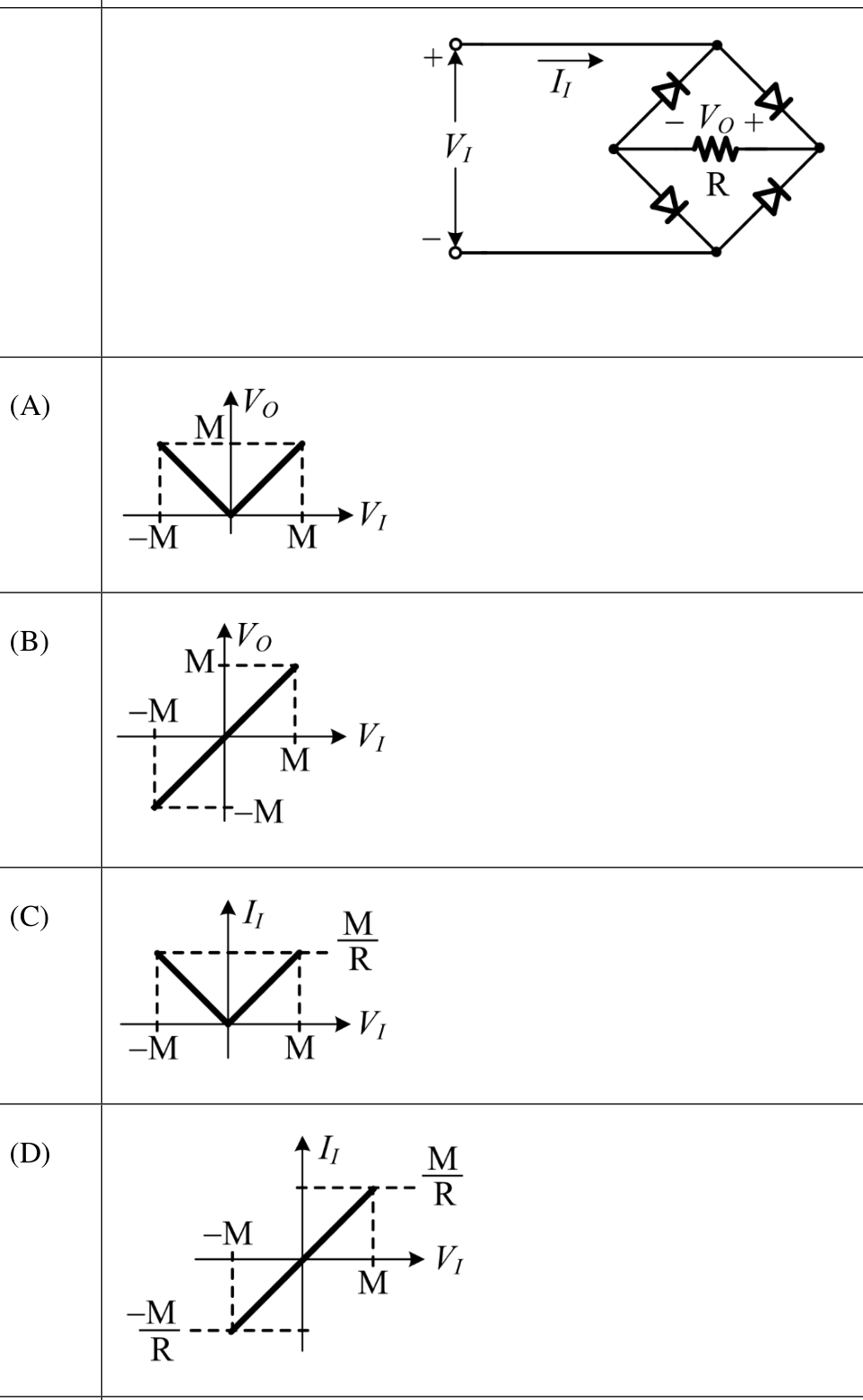
The diodes form a full-wave bridge: the two diodes with their cathodes on the right node conduct from the input terminal that is positive, and the load current always enters the load from the right, so $V_O=+|V_I|$ (plot A; ideal diodes drop nothing). The input current is $+V_I/R$ when $V_I>0$ and reverses direction when $V_I<0$, so $I_I=V_I/R$, a straight line through the origin (plot D). Plot B ($V_O=V_I$) and plot C ($I_I=|V_I|/R$) would need the current to keep the same direction for both polarities, which the bridge does not do.
More Diode Circuits questions
GATE 2025 EC Q61– The diode in the circuit shown below is ideal. The input voltage (in Volts) is given by V…
GATE 2024 EC Q23– In the circuit shown, the n:1 step-down transformer and the diodes are ideal. The diodes…
GATE 2024 EC Q35– As shown in the circuit, the initial voltage across the capacitor is 10 V, with the switch…
GATE 2023 EC Q40– In the circuit shown below, D 1 and D 2 are silicon diodes with cut-in voltage of 0.7 V. V…
GATE 2022 EC Q57– A circuit and the characteristics of the diode (D) in it are shown. The ratio of the…
GATE 2021 EC Q53– An asymmetrical periodic pulse train v in of 10 V amplitude with on-time T ON=1 ms and…