GATE 2023 EC – Question 40
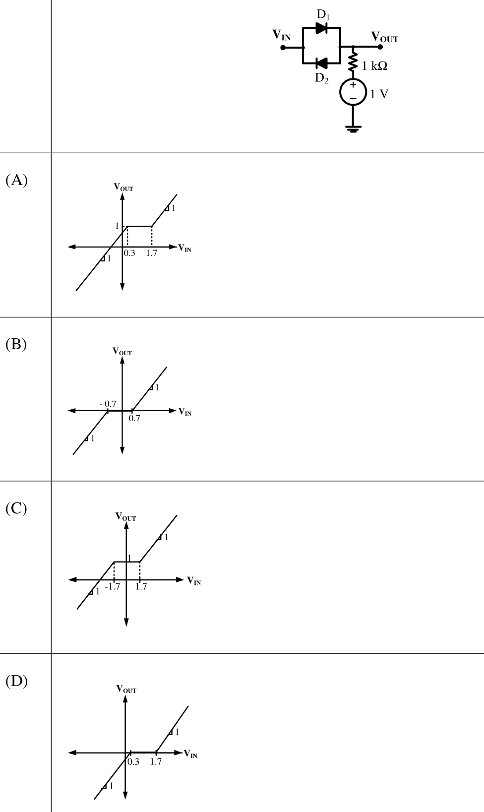
In the circuit shown below, $D_1$ and $D_2$ are silicon diodes with cut-in voltage of 0.7 V. $V_{IN}$ and $V_{OUT}$ are input and output voltages in volts. The transfer characteristic is
Practise this question in The GATE Grind →
Show answer and explanation
Correct answer: (A) Plot (A)
Explanation
$V_{OUT}$ is the node joining the two anti-parallel diodes to the 1 kΩ resistor, whose far end is held at 1 V, and nothing else loads it. If $V_{IN}>1.7$ V, $D_1$ conducts and $V_{OUT}=V_{IN}-0.7$. If $V_{IN}<0.3$ V, $D_2$ conducts and $V_{OUT}=V_{IN}+0.7$. For $0.3\le V_{IN}\le1.7$ V neither diode conducts, no current flows in the resistor and $V_{OUT}=1$ V. That is a unit-slope line with a flat region at 1 V from 0.3 V to 1.7 V: plot (A).