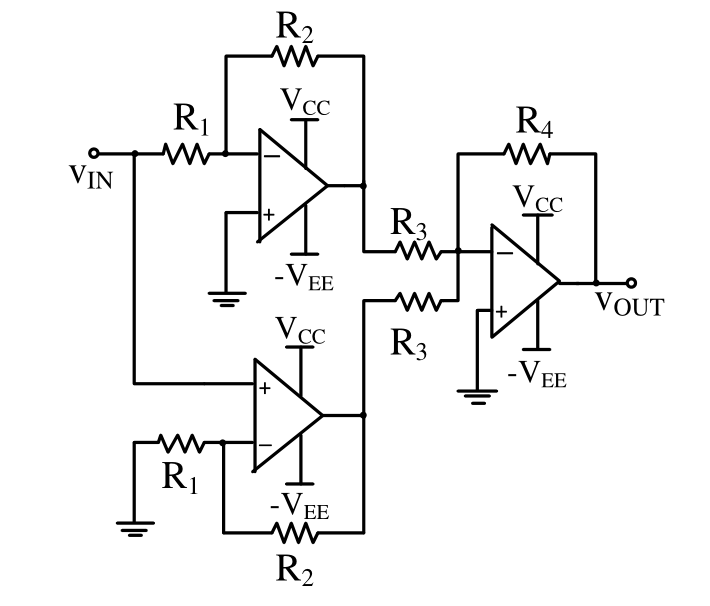
The top op-amp is an inverting amplifier: $V_1=-\dfrac{R_2}{R_1}V_{IN}$. The lower op-amp is non-inverting: $V_2=\left(1+\dfrac{R_2}{R_1}\right)V_{IN}$. The last stage is an inverting summer with equal input resistors $R_3$: $V_{OUT}=-\dfrac{R_4}{R_3}(V_1+V_2)=-\dfrac{R_4}{R_3}\left(-\dfrac{R_2}{R_1}+1+\dfrac{R_2}{R_1}\right)V_{IN}=-\dfrac{R_4}{R_3}V_{IN}$.
More Op-amp Circuits questions
GATE 2022 EC Q26– An ideal OPAMP circuit with a sinusoidal input is shown in the figure. The 3 dB frequency…
GATE 2022 EC Q41– For the following circuit with an ideal OPAMP, the difference between the maximum and the…
GATE 2022 EC Q42– A circuit with an ideal OPAMP is shown. The Bode plot for the magnitude (in dB) of the…
GATE 2022 EC Q58– Consider the circuit shown with an ideal OPAMP. The output voltage V 0 is V (rounded off…
GATE 2021 EC Q19– For the circuit with an ideal OPAMP shown in the figure, V REF is fixed. If V OUT=1 volt…
GATE 2021 EC Q20– Consider the circuit with an ideal OPAMP shown in the figure. Assuming V IN V CC and V REF…