Analog Circuits · Diode Circuits · 1 mark · Numerical answer
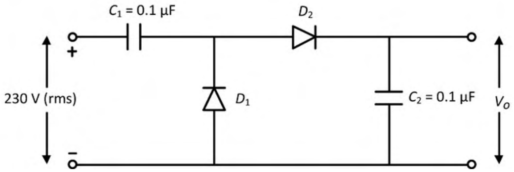
In the circuit shown below, all the components are ideal and the input voltage is sinusoidal. The magnitude of the steady-state output $V_o$ (rounded off to two decimal places) is ________ V.
This is a voltage doubler. In the negative half-cycle, $D_1$ conducts and $C_1$ charges to the peak $V_m=230\sqrt2=325.27$ V. In the positive half-cycle the source and $C_1$ add, and $D_2$ charges $C_2$ to $2V_m$. So $V_o=2\times325.27=650.5$ V.
More Diode Circuits questions
GATE 2019 EC Q34– In the circuit shown, V s is a square wave of period T with maximum and minimum values of…
GATE 2019 EC Q48– In the circuit shown, the breakdown voltage and the maximum current of the Zener diode are…
GATE 2019 EC Q62– In the circuit shown, V s is a 10 V square wave of period T=4 ms with R=500\ and C=10\ F.…
GATE 2018 EC Q36– The circuit shown in the figure is used to provide regulated voltage (5 V) across the 1\ k…
GATE 2015 EC Q21– For the circuit with ideal diodes shown in the figure, the shape of the output (v out) for…
GATE 2015 EC Q22– In the circuit shown below, the Zener diode is ideal and the Zener voltage is 6 V. The…